
User Manual


Camera interfaces
Guppy PRO Technical Manual V4.0.0
83
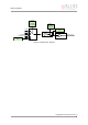
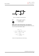
Output modes
PinState 0 switches off the output transistor and produces a low level over
the resistor connected from the output to ground.
The following diagram illustrates the dependencies of the various output sig-
nals.
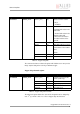
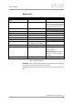
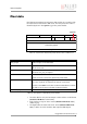
ID Mode Default / description
0x00 Off
0x01 Output state follows PinState bit Using this mode, the Polarity bit
has to be set to 0 (not inverted).
This is necessary for an error free
display of the output status.
0x02 Integration enable
Output 1
0x03 Reserved
0x04 Reserved
0x05 Reserved
0x06 FrameValid
0x07 Busy
Output 2
0x08 Follow corresponding input
(Inp1 Out1, Inp2 Out2)
0x09 PWM (=pulse-width modulation) Guppy PRO housing models
0x0A WaitingForTrigger Only in Trigger Edge Mode.
All other Mode = 0
WaitingForTrigger is useful to
know, if a new trigger will be
accepted.
0x0B..0x1F Reserved
Table 30: Output routing