
User Manual

Description of the data path
Guppy PRO Technical Manual V4.0.0
94
Description of the data path
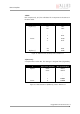
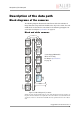
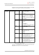
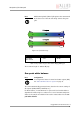
Block diagrams of the cameras
The following diagrams illustrate the data flow and the bit resolution of
image data after being read from the CCD sensor chip in the camera. The indi-
vidual blocks are described in more detail in the following paragraphs. For
sensor data see Chapter Specifications on page 38.
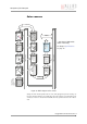
Black and white cameras
Setting LUT = OFF effectively makes full use of the 14 bit by bypassing the LUT circuitry; set-
ting LUT = ON means that the most significant 12 bit of the 14 bit are used and further down
converted to 10 bit. For cameras with 12-bit ADC: the most significant 10 bit of the 12 bit are
used.
Figure 37: Block diagram b/w camera
Sensor
Analog
Gain
Analog
Offset
Analog
ADC
IEEE 1394b
interface
1394b
14 bit
Defect pixel
correction
(only CMOS)
14 bit
Camera control
HIROSE I/O
RS232
8 Bit
Frame
memory
14 bit 14 bit
14 bit
LUT
12
10
14 bit
CMOS: the following
functions are integrated in
sensor:
Binning, sub-sampling,
horizontal masking
Horizontal
sub-sampling
(only CCD)
Horizontal
binning
(only CCD)
Horizontal
masking
(only CCD)
*
* Some Guppy PRO models
deliver 12 bit only.
See Chapter Specifications
on page 38.