
Instruction manual


Marlin Technical ManualV.2.7.0
193
Configuration of the camera
Feature control error status register
Video mode control and status registers for
Format_7
Quadlet offset Format_7 Mode_0
The quadlet offset to the base address for Format_7 Mode_0, which can be read
out at F0F002E0h (according to Table 88: Frame rate inquiry register on page
173) gives 003C2000h.
4 x 3C2000h = F08000h so that the base address for the latter (Table 95: For-
mat_7 control and status register on page 193) equals to
F0000000h + F08000h = F0F08000h.
Quadlet offset Format_7 Mode_1
The quadlet offset to the base address for Format_7 Mode_1, which can be read
out at F0F002E4h (according to Table 88: Frame rate inquiry register on page
173) gives 003C2400h.
4 x 003C2400h = F09000h so that the base address for the latter (Table 95: For-
mat_7 control and status register on page 193) equals to
F0000000h + F09000h = F0F09000h.
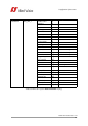
Format_7 control and status register (CSR)
Offset Name Notes
640h Feature_Control_Error_Status_HI always 0
644h Feature_Control_Error_Status_LO always 0
Table 94: Feature control error register
Offset Name Notes
000h MAX_IMAGE_SIZE_INQ According to IIDC V1.3
004h UNIT_SIZE_INQ According to IIDC V1.3
008h IMAGE_POSITION According to IIDC V1.3
00Ch IMAGE_SIZE According to IIDC V1.3
010h COLOR_CODING_ID See note
014h COLOR_CODING_INQ According to IIDC V1.3
034h PIXEL_NUMER_INQ According to IIDC V1.3
038h TOTAL_BYTES_HI_INQ According to IIDC V1.3
03Ch TOTAL_BYTES_LO_INQ According to IIDC V1.3
Table 95: Format_7 control and status register