
Specifications


9
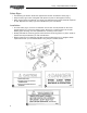
Assembly - 7420, 8420 & 8420G Snowblower
Assembly Instructions
1. 740: Turn the bottom tube weldments (907213) as shown in drawing and slide them into the
sleeve welded to the main body.
840 & 840G: Turn the bottom tubes (907250) as shown in drawing and slide them into the
sleeve welded to the main body.
All sizes: The correct position for each individual tractor will be determined when mounting the
snowblower on the tractor. These tubes are connected to the sleeves with a 3/4" x 4-1/4" pin
(816131) and a hair pin clip (961012).
2. 740: Bolt the left (815263) and the right (815264) A-frames to the inside of the plates welded
to the hitch tubes using 7/8" x 2-1/2" hex bolts (966527) and lock nuts. Join the top of the hitch
arms by bolting a 1" O.D. x 2" spacer (965808) between the top plates using a 3/4" x 4" bolt
(84336), lock washer (81701) and hex nut (81700) through the lower outside holes. Bolt the
upper hitch tube weldment 907218 (907221) between the same plates using the same size of
bolt. Use the inside holes on the top plates for the upper tube. The other end of the top hitch
tube bolts between the welded brackets on the top edge of the fan housing with the same
hardware. Tube must be turned as shown in drawing. Tighten all hardware.
840 & 840G: Turn the hitch weldments (F0463) as shown in drawing. Bolt the hitch to the two
bottom tubes (907250) using 7/8" x 5" bolts (811826) and lock nuts. The upper hitch tube 907218
(907221) bolts to the top of the hitch and the welded brackets on the top edge of the fan
housing using 3/4" x 4" bolts (#84336), lock washers (81701) and hex nuts (81700). Tube must
be turned as shown in drawing. Join the top of the hitch arms by bolting a 1" O.D. x 2" spacer
(965808) between the top plates using a 3/4" x 4" bolt, lock washer and hex nut through the
lower outside holes. Tighten all hardware.
3. 740: A Category 1 top link pin (965807) is fitted in the top holes of the hitch arm plates. This pin
is used for standard three-point hitch only. The bushing in the lower holes is used for the quick
hitch.
840 & 840G: The hitch fits standard Category 1 and 2 three-point hitches as well as Category 1
and 2 quick hitches. The highest and lowest holes are for standard three-point only. The inside
set of holes must be used for a quick hitch. Adaptor bushings are supplied to convert from
Category 1 or 2.
4. Mount the discharge spout (815903) using the spacers and spout clamps (815911 & 815912)
bolted to the spout ring on the snowblower. Lubricate the spout ring and clamps.
5. Hydraulic Spout Swivel:
- Mount the swivel arm (907820) onto the swivel pin welded to the back corner of the fan
housing using a 1" I.D. washer (967140) and a 3/16" x 1-1/2" cotter pin (9812433).
- Wrap cable (965832) around spout and clamp to the ends of the swivel using 3/16" cable
clamps (965806).
- With the swivel in extended position (i.e. cylinder fully extended) and the spout turned
to the right, clamp the cable to the spout cable anchor using a 1/4" cable clamp (961658).
Ensure that the spout is not jammed and that there is no slack in the cable.
- Use a standard 8" stroke cylinder (20-1/4" min., 28-1/4" max. pin centers).
- NOTE: A hydraulic cylinder and hose kit to control the spout deflector is available as an
option.