
Instruction manual


AVT Prosilica GS Technical Manual V2.0.0
28
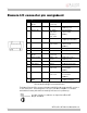
Camera Out 1 and Camera Out 2
These signals (GPOut) only function as outputs and can be configured as follows:
Exposing Corresponds to when camera is integrating light.
Trigger Ready Indicates when the camera will accept a trigger signal.
Trigger Inpu
t
A relay of the trigger input signal used to “daisy chain” the
trigger signal for multiple cameras.
Readou
t
Valid when camera is reading out data.
Imaging Valid when camera is exposing or reading out.
Strobe Programmable pulse based on one of the above events.
GPO User programmable binary output.
Any of the above signals can be set for active high or active low.
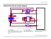
GPOut 1 is isolated and should be used in noisy environments. GPOut2 is non-isolated
and can be used when environmental noise is not a problem and when faster response is
required.
GPOut1 will require a pull up resistor of greater than 1Kohm to the user’s 5V logic
supply. Review circuit diagrams for more information.
RxD RS-232 and TxD RS-232
These signals are RS-232 compatible. These signals allow communication from the host
system via the Ethernet port to a peripheral device connected to the camera. Note that
these signals are not isolated and therefore careful attention should be used when
designing cabling in noisy environments.
Isolated Ground
The isolated ground must be connected to the user’s external circuit ground if GPIn1 or
GPOut1 is being used.
Non-isolated Ground
This ground connection must be connected to the user’s external circuit ground if GPIn2
or GPOut2 is to be used or if the RS-232 port is to be used. Note that non-isolated
Ground is common with External (power) Ground however it is good practice to provide a
separate ground connection for power and signaling when designing the cabling.