
Instruction manual
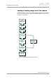
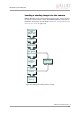
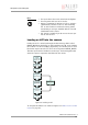
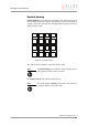
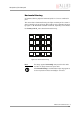
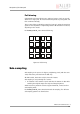
Table Of Contents
- Introduction
- Declarations of conformity
- Safety instructions
- PIKE types and highlights
- FireWire
- Overview
- FireWire in detail
- Serial bus
- FireWire connection capabilities
- Capabilities of 1394a (FireWire 400)
- Capabilities of 1394b (FireWire 800)
- Compatibility between 1394a and 1394b
- Image transfer via 1394a and 1394b
- 1394b bandwidths
- FireWire Plug & play capabilities
- FireWire hot plug precautions
- Operating system support
- 1394a/b comparison
- System components
- Specifications
- Camera dimensions
- PIKE standard housing (2 x 1394b copper)
- PIKE (1394b: 1 x GOF, 1 x copper)
- Tripod adapter
- Pike W90 (2 x 1394b copper)
- Pike W90 (1394b: 1 x GOF, 1 x copper)
- Pike W90 S90 (2 x 1394b copper)
- Pike W90 S90 (1394b: 1 x GOF, 1 x copper)
- Pike W270 (2 x 1394b copper)
- Pike W270 (1394b: 1 x GOF, 1 x copper)
- Pike W270 S90 (2 x 1394b copper)
- Pike W270 S90 (1394b: 1 x GOF, 1 x copper)
- Cross section: C-Mount (VGA size filter)
- Cross section: C-Mount (large filter)
- Adjustment of C-Mount
- F-Mount, K-Mount, M39-Mount
- Camera interfaces
- Description of the data path
- Block diagrams of the cameras
- Sensor
- Channel balance
- White balance
- Auto shutter
- Auto gain
- Manual gain
- Brightness (black level or offset)
- Horizontal mirror function
- Shading correction
- Look-up table (LUT) and gamma function
- Binning (b/w models)
- Sub-sampling
- High SNR mode (High Signal Noise Ratio)
- Frame memory and deferred image transport
- Color interpolation (BAYER demosaicing)
- Sharpness
- Hue and saturation
- Color correction
- Color conversion (RGB ‡ YUV)
- Bulk Trigger
- Level Trigger
- Serial interface
- Controlling image capture
- Video formats, modes and bandwidth
- How does bandwidth affect the frame rate?
- Configuration of the camera
- Camera_Status_Register
- Configuration ROM
- Implemented registers
- Camera initialize register
- Inquiry register for video format
- Inquiry register for video mode
- Inquiry register for video frame rate and base address
- Inquiry register for basic function
- Inquiry register for feature presence
- Inquiry register for feature elements
- Inquiry register for absolute value CSR offset address
- Status and control register for feature
- Feature control error status register
- Video mode control and status registers for Format_7
- Advanced features
- Version information inquiry
- Advanced feature inquiry
- Camera status
- Maximum resolution
- Time base
- Extended shutter
- Test images
- Look-up tables (LUT)
- Shading correction
- Deferred image transport
- Frame information
- Input/output pin control
- Delayed Integration enable
- Auto shutter control
- Auto gain control
- Autofunction AOI
- Color correction
- Trigger delay
- Mirror image
- AFE channel compensation (channel balance)
- Soft Reset
- High SNR mode (High Signal Noise Ratio)
- User profiles
- GPDATA_BUFFER
- Firmware update
- Glossary
- Index
Description of the data path
PIKE Technical Manual V3.1.0
124
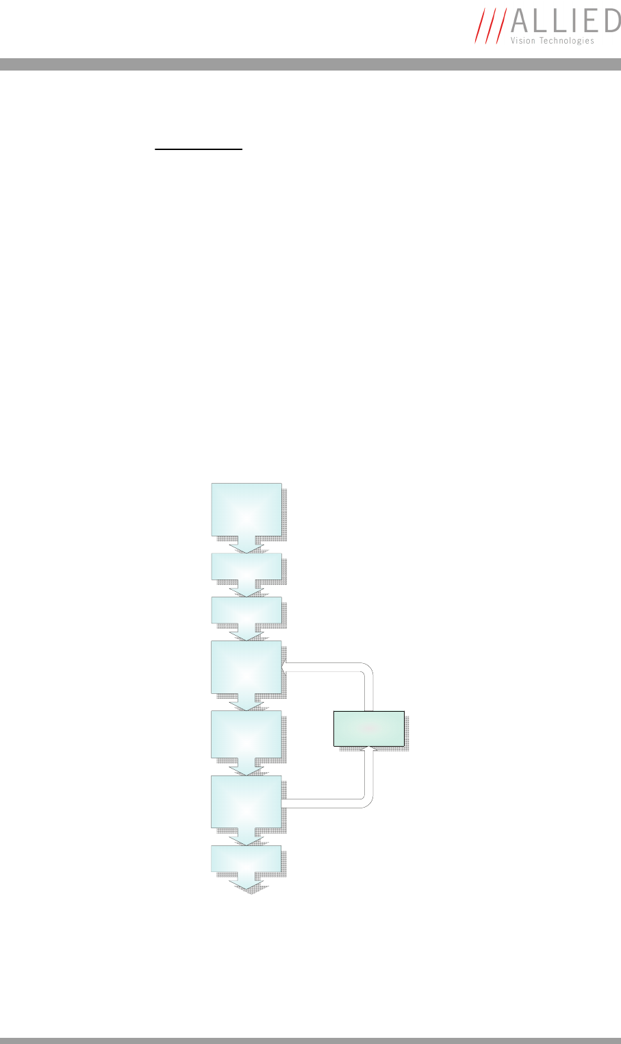
Loading an LUT into the camera
Loading the LUT is carried out through the data exchange buffer called
GPDATA_BUFFER. As this buffer can hold a maximum of 2 kB, and a complete
LUT at 16384 x 14 bit is 28 kByte, programming can not take place in a one
block write step because the size of an LUT is larger than GPDATA_BUFFER.
Therefore input must be handled in several steps. The flow diagram below
shows the sequence required to load data into the camera.
To configure this feature in an advanced register: See Table 118: LUT control
register on page 227.
Note
L
• The input value is the 14-bit value from the digitizer.
• The two gamma LUTs use LUT 14 and 15.
• Gamma 1 (gamma=0.7) switches on LUT 14, gamma 2
(gamma=0.45) switches on LUT 15. After overriding
LUT 14 and 15 with a user defined content, gamma
functionality is no longer available until the next full
initialization of the camera.
• LUT content is volatile if you do not use the user pro-
files to save the LUT.
Figure 66: Loading an LUT
Query limits from
register:
LUT_INFO and
GPDATA_INFO
Set EnableMemWR
to true (1)
Set AddrOffset to 0
Write n databytes
in
GPDATA_BUFFER
Offset is increased
in camera after n
bytes are written
Check
EnableMemWR for
no change
Repeat steps until
all data is written
Set EnableMemWR
to false (0)