
Instruction manual
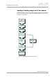
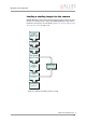
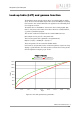
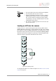
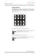
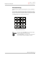
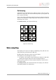
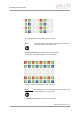
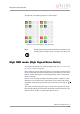
Table Of Contents
- Introduction
- Declarations of conformity
- Safety instructions
- PIKE types and highlights
- FireWire
- Overview
- FireWire in detail
- Serial bus
- FireWire connection capabilities
- Capabilities of 1394a (FireWire 400)
- Capabilities of 1394b (FireWire 800)
- Compatibility between 1394a and 1394b
- Image transfer via 1394a and 1394b
- 1394b bandwidths
- FireWire Plug & play capabilities
- FireWire hot plug precautions
- Operating system support
- 1394a/b comparison
- System components
- Specifications
- Camera dimensions
- PIKE standard housing (2 x 1394b copper)
- PIKE (1394b: 1 x GOF, 1 x copper)
- Tripod adapter
- Pike W90 (2 x 1394b copper)
- Pike W90 (1394b: 1 x GOF, 1 x copper)
- Pike W90 S90 (2 x 1394b copper)
- Pike W90 S90 (1394b: 1 x GOF, 1 x copper)
- Pike W270 (2 x 1394b copper)
- Pike W270 (1394b: 1 x GOF, 1 x copper)
- Pike W270 S90 (2 x 1394b copper)
- Pike W270 S90 (1394b: 1 x GOF, 1 x copper)
- Cross section: C-Mount (VGA size filter)
- Cross section: C-Mount (large filter)
- Adjustment of C-Mount
- F-Mount, K-Mount, M39-Mount
- Camera interfaces
- Description of the data path
- Block diagrams of the cameras
- Sensor
- Channel balance
- White balance
- Auto shutter
- Auto gain
- Manual gain
- Brightness (black level or offset)
- Horizontal mirror function
- Shading correction
- Look-up table (LUT) and gamma function
- Binning (b/w models)
- Sub-sampling
- High SNR mode (High Signal Noise Ratio)
- Frame memory and deferred image transport
- Color interpolation (BAYER demosaicing)
- Sharpness
- Hue and saturation
- Color correction
- Color conversion (RGB ‡ YUV)
- Bulk Trigger
- Level Trigger
- Serial interface
- Controlling image capture
- Video formats, modes and bandwidth
- How does bandwidth affect the frame rate?
- Configuration of the camera
- Camera_Status_Register
- Configuration ROM
- Implemented registers
- Camera initialize register
- Inquiry register for video format
- Inquiry register for video mode
- Inquiry register for video frame rate and base address
- Inquiry register for basic function
- Inquiry register for feature presence
- Inquiry register for feature elements
- Inquiry register for absolute value CSR offset address
- Status and control register for feature
- Feature control error status register
- Video mode control and status registers for Format_7
- Advanced features
- Version information inquiry
- Advanced feature inquiry
- Camera status
- Maximum resolution
- Time base
- Extended shutter
- Test images
- Look-up tables (LUT)
- Shading correction
- Deferred image transport
- Frame information
- Input/output pin control
- Delayed Integration enable
- Auto shutter control
- Auto gain control
- Autofunction AOI
- Color correction
- Trigger delay
- Mirror image
- AFE channel compensation (channel balance)
- Soft Reset
- High SNR mode (High Signal Noise Ratio)
- User profiles
- GPDATA_BUFFER
- Firmware update
- Glossary
- Index

Description of the data path
PIKE Technical Manual V3.1.0
130
The different sub-sampling patterns are shown below.
High SNR mode (High Signal Noise Ratio)
To configure this feature in an advanced register: See Table 132: High Signal
Noise Ratio (HSNR) on page 242.
In this mode the camera grabs and averages a set number of images and out-
puts one image with the same bit depth and the same brightness. This means
that the camera will output an 8-bit averaged image when an 8-bit image
format is selected.
Because of the fact that normally uncorrelated (photon-, amplifier-) noise
dominates over correlated noise (fixed pattern noise), adding two images
will double (6 dB) the gray levels but only increase the noise levels by
(3 dB).
This enhances both the dynamic range as well as the signal-to-noise ratio.
Consequently adding 256 8-bit images will lead to a potential signal-to-noise
enhancement of 24 dB or a resulting bit depth of 16 bit.
Figure 72: H+V sub-sampling: (b/w and color)
Note
L
Changing sub-sampling modes involves the generation of new
shading reference images due to a change in the image size.
2