
Instruction manual
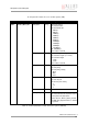
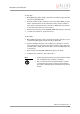
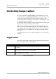
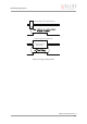
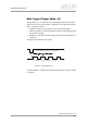

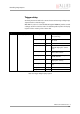
Table Of Contents
- Introduction
- Declarations of conformity
- Safety instructions
- PIKE types and highlights
- FireWire
- Overview
- FireWire in detail
- Serial bus
- FireWire connection capabilities
- Capabilities of 1394a (FireWire 400)
- Capabilities of 1394b (FireWire 800)
- Compatibility between 1394a and 1394b
- Image transfer via 1394a and 1394b
- 1394b bandwidths
- FireWire Plug & play capabilities
- FireWire hot plug precautions
- Operating system support
- 1394a/b comparison
- System components
- Specifications
- Camera dimensions
- PIKE standard housing (2 x 1394b copper)
- PIKE (1394b: 1 x GOF, 1 x copper)
- Tripod adapter
- Pike W90 (2 x 1394b copper)
- Pike W90 (1394b: 1 x GOF, 1 x copper)
- Pike W90 S90 (2 x 1394b copper)
- Pike W90 S90 (1394b: 1 x GOF, 1 x copper)
- Pike W270 (2 x 1394b copper)
- Pike W270 (1394b: 1 x GOF, 1 x copper)
- Pike W270 S90 (2 x 1394b copper)
- Pike W270 S90 (1394b: 1 x GOF, 1 x copper)
- Cross section: C-Mount (VGA size filter)
- Cross section: C-Mount (large filter)
- Adjustment of C-Mount
- F-Mount, K-Mount, M39-Mount
- Camera interfaces
- Description of the data path
- Block diagrams of the cameras
- Sensor
- Channel balance
- White balance
- Auto shutter
- Auto gain
- Manual gain
- Brightness (black level or offset)
- Horizontal mirror function
- Shading correction
- Look-up table (LUT) and gamma function
- Binning (b/w models)
- Sub-sampling
- High SNR mode (High Signal Noise Ratio)
- Frame memory and deferred image transport
- Color interpolation (BAYER demosaicing)
- Sharpness
- Hue and saturation
- Color correction
- Color conversion (RGB ‡ YUV)
- Bulk Trigger
- Level Trigger
- Serial interface
- Controlling image capture
- Video formats, modes and bandwidth
- How does bandwidth affect the frame rate?
- Configuration of the camera
- Camera_Status_Register
- Configuration ROM
- Implemented registers
- Camera initialize register
- Inquiry register for video format
- Inquiry register for video mode
- Inquiry register for video frame rate and base address
- Inquiry register for basic function
- Inquiry register for feature presence
- Inquiry register for feature elements
- Inquiry register for absolute value CSR offset address
- Status and control register for feature
- Feature control error status register
- Video mode control and status registers for Format_7
- Advanced features
- Version information inquiry
- Advanced feature inquiry
- Camera status
- Maximum resolution
- Time base
- Extended shutter
- Test images
- Look-up tables (LUT)
- Shading correction
- Deferred image transport
- Frame information
- Input/output pin control
- Delayed Integration enable
- Auto shutter control
- Auto gain control
- Autofunction AOI
- Color correction
- Trigger delay
- Mirror image
- AFE channel compensation (channel balance)
- Soft Reset
- High SNR mode (High Signal Noise Ratio)
- User profiles
- GPDATA_BUFFER
- Firmware update
- Glossary
- Index

Controlling image capture
PIKE Technical Manual V3.1.0
145
Controlling image capture
The cameras support the SHUTTER_MODES specified in IIDC V1.31. For all
models this shutter is a global pipelined shutter; meaning that all pixels are
exposed to the light at the same moment and for the same time span.
Pipelined means that the shutter for a new image can already happen, while
the preceding image is transmitted.
In continuous modes the shutter is opened shortly before the vertical reset
happens, thus acting in a frame-synchronous way.
Combined with an external trigger, it becomes asynchronous in the sense
that it occurs whenever the external trigger occurs. Individual images are
recorded when an external trigger impulse is present. This ensures that even
fast moving objects can be grabbed with no image lag and with minimal
image blur.
The external trigger is fed as a TTL signal through Pin 4 of the camera I/O
connector.
Trigger modi
The cameras support IIDC conforming Trigger_Mode_0 and Trigger_Mode_1
and special Trigger_Mode_15 (bulk trigger).
Trigger Mode Description
Trigger_Mode_0 Sets the shutter time according to the value set in the shutter (or extended shut-
ter) register
Trigger_Mode_1 Sets the shutter time according to the active low time of the pulse applied (or
active high time in the case of an inverting input)
Trigger_Mode_15 Is a bulk trigger, combining one external trigger event with continuous or one-
shot or multishot internal trigger
Table 55: Trigger modi