
Instruction manual
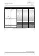
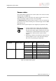
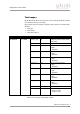
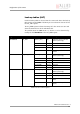
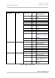
Table Of Contents
- Introduction
- Declarations of conformity
- Safety instructions
- PIKE types and highlights
- FireWire
- Overview
- FireWire in detail
- Serial bus
- FireWire connection capabilities
- Capabilities of 1394a (FireWire 400)
- Capabilities of 1394b (FireWire 800)
- Compatibility between 1394a and 1394b
- Image transfer via 1394a and 1394b
- 1394b bandwidths
- FireWire Plug & play capabilities
- FireWire hot plug precautions
- Operating system support
- 1394a/b comparison
- System components
- Specifications
- Camera dimensions
- PIKE standard housing (2 x 1394b copper)
- PIKE (1394b: 1 x GOF, 1 x copper)
- Tripod adapter
- Pike W90 (2 x 1394b copper)
- Pike W90 (1394b: 1 x GOF, 1 x copper)
- Pike W90 S90 (2 x 1394b copper)
- Pike W90 S90 (1394b: 1 x GOF, 1 x copper)
- Pike W270 (2 x 1394b copper)
- Pike W270 (1394b: 1 x GOF, 1 x copper)
- Pike W270 S90 (2 x 1394b copper)
- Pike W270 S90 (1394b: 1 x GOF, 1 x copper)
- Cross section: C-Mount (VGA size filter)
- Cross section: C-Mount (large filter)
- Adjustment of C-Mount
- F-Mount, K-Mount, M39-Mount
- Camera interfaces
- Description of the data path
- Block diagrams of the cameras
- Sensor
- Channel balance
- White balance
- Auto shutter
- Auto gain
- Manual gain
- Brightness (black level or offset)
- Horizontal mirror function
- Shading correction
- Look-up table (LUT) and gamma function
- Binning (b/w models)
- Sub-sampling
- High SNR mode (High Signal Noise Ratio)
- Frame memory and deferred image transport
- Color interpolation (BAYER demosaicing)
- Sharpness
- Hue and saturation
- Color correction
- Color conversion (RGB ‡ YUV)
- Bulk Trigger
- Level Trigger
- Serial interface
- Controlling image capture
- Video formats, modes and bandwidth
- How does bandwidth affect the frame rate?
- Configuration of the camera
- Camera_Status_Register
- Configuration ROM
- Implemented registers
- Camera initialize register
- Inquiry register for video format
- Inquiry register for video mode
- Inquiry register for video frame rate and base address
- Inquiry register for basic function
- Inquiry register for feature presence
- Inquiry register for feature elements
- Inquiry register for absolute value CSR offset address
- Status and control register for feature
- Feature control error status register
- Video mode control and status registers for Format_7
- Advanced features
- Version information inquiry
- Advanced feature inquiry
- Camera status
- Maximum resolution
- Time base
- Extended shutter
- Test images
- Look-up tables (LUT)
- Shading correction
- Deferred image transport
- Frame information
- Input/output pin control
- Delayed Integration enable
- Auto shutter control
- Auto gain control
- Autofunction AOI
- Color correction
- Trigger delay
- Mirror image
- AFE channel compensation (channel balance)
- Soft Reset
- High SNR mode (High Signal Noise Ratio)
- User profiles
- GPDATA_BUFFER
- Firmware update
- Glossary
- Index

Configuration of the camera
PIKE Technical Manual V3.1.0
223
Maximum resolution
This register indicates the highest resolution for the sensor and is read-only.
This register normally outputs the MAX_IMAGE_SIZE_INQ Format_7 Mode_0
value.
Time base
Corresponding to IIDC, exposure time is set via a 12-bit value in the corre-
sponding register (SHUTTER_INQ [51Ch] and SHUTTER [81Ch]).
This means that a value in the range of 1 to 4095 can be entered.
PIKE cameras use a time base which is multiplied by the shutter register
value. This multiplier is configured as the time base via the TIMEBASE regis-
ter.
The time base IDs 0-9 are in bits 28 to 31. See Table 115: Time base ID on
page 224.
Default time base is 20 µs: This means that the integration time can be
changed in 20 µs increments with the shutter control.
Register Name Field Bit Description
0xF1000200 MAX_RESOLUTION MaxHeight [0..15] Sensor height
(read only)
MaxWidth [16..31] Sensor width
(read only)
Table 113: Max. resolution inquiry register
Register Name Field Bit Description
0xF1000208 TIMEBASE Presence_Inq [0] Indicates presence of this
feature (read only)
--- [1..7] Reserved
ExpOffset [8..19] Exposure offset in µs
--- [20..27] Reserved
Timebase_ID [28..31] See Table 115: Time base ID
on page 224.
Table 114: Time base configuration register