
Instruction manual

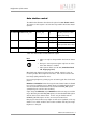
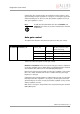

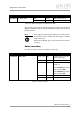
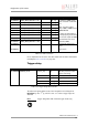
Table Of Contents
- Introduction
- Declarations of conformity
- Safety instructions
- PIKE types and highlights
- FireWire
- Overview
- FireWire in detail
- Serial bus
- FireWire connection capabilities
- Capabilities of 1394a (FireWire 400)
- Capabilities of 1394b (FireWire 800)
- Compatibility between 1394a and 1394b
- Image transfer via 1394a and 1394b
- 1394b bandwidths
- FireWire Plug & play capabilities
- FireWire hot plug precautions
- Operating system support
- 1394a/b comparison
- System components
- Specifications
- Camera dimensions
- PIKE standard housing (2 x 1394b copper)
- PIKE (1394b: 1 x GOF, 1 x copper)
- Tripod adapter
- Pike W90 (2 x 1394b copper)
- Pike W90 (1394b: 1 x GOF, 1 x copper)
- Pike W90 S90 (2 x 1394b copper)
- Pike W90 S90 (1394b: 1 x GOF, 1 x copper)
- Pike W270 (2 x 1394b copper)
- Pike W270 (1394b: 1 x GOF, 1 x copper)
- Pike W270 S90 (2 x 1394b copper)
- Pike W270 S90 (1394b: 1 x GOF, 1 x copper)
- Cross section: C-Mount (VGA size filter)
- Cross section: C-Mount (large filter)
- Adjustment of C-Mount
- F-Mount, K-Mount, M39-Mount
- Camera interfaces
- Description of the data path
- Block diagrams of the cameras
- Sensor
- Channel balance
- White balance
- Auto shutter
- Auto gain
- Manual gain
- Brightness (black level or offset)
- Horizontal mirror function
- Shading correction
- Look-up table (LUT) and gamma function
- Binning (b/w models)
- Sub-sampling
- High SNR mode (High Signal Noise Ratio)
- Frame memory and deferred image transport
- Color interpolation (BAYER demosaicing)
- Sharpness
- Hue and saturation
- Color correction
- Color conversion (RGB ‡ YUV)
- Bulk Trigger
- Level Trigger
- Serial interface
- Controlling image capture
- Video formats, modes and bandwidth
- How does bandwidth affect the frame rate?
- Configuration of the camera
- Camera_Status_Register
- Configuration ROM
- Implemented registers
- Camera initialize register
- Inquiry register for video format
- Inquiry register for video mode
- Inquiry register for video frame rate and base address
- Inquiry register for basic function
- Inquiry register for feature presence
- Inquiry register for feature elements
- Inquiry register for absolute value CSR offset address
- Status and control register for feature
- Feature control error status register
- Video mode control and status registers for Format_7
- Advanced features
- Version information inquiry
- Advanced feature inquiry
- Camera status
- Maximum resolution
- Time base
- Extended shutter
- Test images
- Look-up tables (LUT)
- Shading correction
- Deferred image transport
- Frame information
- Input/output pin control
- Delayed Integration enable
- Auto shutter control
- Auto gain control
- Autofunction AOI
- Color correction
- Trigger delay
- Mirror image
- AFE channel compensation (channel balance)
- Soft Reset
- High SNR mode (High Signal Noise Ratio)
- User profiles
- GPDATA_BUFFER
- Firmware update
- Glossary
- Index

Configuration of the camera
PIKE Technical Manual V3.1.0
231
Reading or writing shading image from/into the camera
Accessing the shading image inside the camera is done through the
GPDATA_BUFFER. Because the size of the GPDATA_BUFFER is smaller than a
whole shading image the data must be written in multiple steps.
To read or write a shading image:
1. Query the limits and ranges by reading SHDG_INFO and GPDATA_INFO.
2. Set EnableMemWR or EnableMemRD to true (1).
3. Set AddrOffset to 0.
4. Write n shading data bytes to GPDATA_BUFFER (n might be lower than
the size of the GPDATA_BUFFER; AddrOffset is automatically adjusted
inside the camera).
5. Repeat step 4 until all data is written into the camera.
6. Set EnableMemWR and EnableMemRD to false.
Automatic generation of a shading image
Shading image data may also be generated by the camera. To use this feature
make sure all settings affecting an image are set properly. The camera uses
the current active resolution to generate the shading image.
To generate a shading image:
1. Set GrabCount to the number of the images to be averaged before the
correction factors are calculated.
2. Set BuildImage to true.
3. Poll the SHDG_CTRL register until the Busy and BuildImage flags are
reset automatically.
The maximum value of GrabCount depends on the camera type and the num-
ber of available image buffers. GrabCount is automatically adjusted to a
power of two.
Do not poll the SHDG_CTRL register too often, while automatic generation is
in progress. Each poll delays the process of generating the shading image.
An optimal poll interval time is 500 ms.
Non-volatile memory operations
Pike cameras support storing shading image data into non-volatile memory.
Once a shading image is stored it is automatically reloaded on each camera
reset.
MaxMemChannel indicates the number of so-called memory channels/slots
available for storing shading images.
To store a shading image into non-volatile memory:
1. Set MemoryChannel to the desired memory channel and
MemoryChannelSave to true (1).
2. Read MemoryChannelError to check for errors.