
Instruction manual

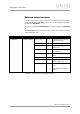
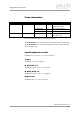
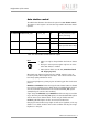
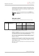

Table Of Contents
- Introduction
- Declarations of conformity
- Safety instructions
- PIKE types and highlights
- FireWire
- Overview
- FireWire in detail
- Serial bus
- FireWire connection capabilities
- Capabilities of 1394a (FireWire 400)
- Capabilities of 1394b (FireWire 800)
- Compatibility between 1394a and 1394b
- Image transfer via 1394a and 1394b
- 1394b bandwidths
- FireWire Plug & play capabilities
- FireWire hot plug precautions
- Operating system support
- 1394a/b comparison
- System components
- Specifications
- Camera dimensions
- PIKE standard housing (2 x 1394b copper)
- PIKE (1394b: 1 x GOF, 1 x copper)
- Tripod adapter
- Pike W90 (2 x 1394b copper)
- Pike W90 (1394b: 1 x GOF, 1 x copper)
- Pike W90 S90 (2 x 1394b copper)
- Pike W90 S90 (1394b: 1 x GOF, 1 x copper)
- Pike W270 (2 x 1394b copper)
- Pike W270 (1394b: 1 x GOF, 1 x copper)
- Pike W270 S90 (2 x 1394b copper)
- Pike W270 S90 (1394b: 1 x GOF, 1 x copper)
- Cross section: C-Mount (VGA size filter)
- Cross section: C-Mount (large filter)
- Adjustment of C-Mount
- F-Mount, K-Mount, M39-Mount
- Camera interfaces
- Description of the data path
- Block diagrams of the cameras
- Sensor
- Channel balance
- White balance
- Auto shutter
- Auto gain
- Manual gain
- Brightness (black level or offset)
- Horizontal mirror function
- Shading correction
- Look-up table (LUT) and gamma function
- Binning (b/w models)
- Sub-sampling
- High SNR mode (High Signal Noise Ratio)
- Frame memory and deferred image transport
- Color interpolation (BAYER demosaicing)
- Sharpness
- Hue and saturation
- Color correction
- Color conversion (RGB ‡ YUV)
- Bulk Trigger
- Level Trigger
- Serial interface
- Controlling image capture
- Video formats, modes and bandwidth
- How does bandwidth affect the frame rate?
- Configuration of the camera
- Camera_Status_Register
- Configuration ROM
- Implemented registers
- Camera initialize register
- Inquiry register for video format
- Inquiry register for video mode
- Inquiry register for video frame rate and base address
- Inquiry register for basic function
- Inquiry register for feature presence
- Inquiry register for feature elements
- Inquiry register for absolute value CSR offset address
- Status and control register for feature
- Feature control error status register
- Video mode control and status registers for Format_7
- Advanced features
- Version information inquiry
- Advanced feature inquiry
- Camera status
- Maximum resolution
- Time base
- Extended shutter
- Test images
- Look-up tables (LUT)
- Shading correction
- Deferred image transport
- Frame information
- Input/output pin control
- Delayed Integration enable
- Auto shutter control
- Auto gain control
- Autofunction AOI
- Color correction
- Trigger delay
- Mirror image
- AFE channel compensation (channel balance)
- Soft Reset
- High SNR mode (High Signal Noise Ratio)
- User profiles
- GPDATA_BUFFER
- Firmware update
- Glossary
- Index

Configuration of the camera
PIKE Technical Manual V3.1.0
240
For an explanation of the color correction matrix and for further information
read Chapter Color correction on page 138.
Trigger delay
The advanced register allows start of the integration to be delayed via
DelayTime by max. 2
21
µs, which is max. 2.1 s after a trigger edge was
detected.
0xF10003A4 COLOR_CORR_COEFFIC11 = Crr [0..31] A number of 1000 equals a
color correction coefficient
of 1.
Color correction values
range -1000..+2000 and are
signed 32 bit.
In order for white balance
to work properly ensure that
the row sum equals to 1000.
The maximum row sum is
limited to 2000.
0xF10003A8 COLOR_CORR_COEFFIC12 = Cgr [0..31]
0xF10003AC COLOR_CORR_COEFFIC13 = Cbr [0..31]
0xF10003B0 COLOR_CORR_COEFFIC21 = Crg [0..31]
0xF10003B4 COLOR_CORR_COEFFIC22 = Cgg [0..31]
0xF10003B8 COLOR_CORR_COEFFIC23 = Cbg [0..31]
0xF10003BC COLOR_CORR_COEFFIC31 = Crb [0..31]
0xF10003C0 COLOR_CORR_COEFFIC32 = Cgb [0..31]
0xF10003C4 COLOR_CORR_COEFFIC33 = Cbb
[0..31]
0xF10003A4
...
0xF10003FC
Reserved for testing pur-
poses
Don’t touch
Register Name Field Bit Description
0xF1000400 TRIGGER_DELAY Presence_Inq [0] Indicates presence of this
feature (read only)
--- [1..5] Reserved
ON_OFF [6] Trigger delay on/off
--- [7..10] Reserved
DelayTime [11..31] Delay time in µs
Table 128: Trigger delay advanced CSR
Note
L
Trigger delay works with external trigger modes only.
Register Name Field Bit Description
Table 127: Color correction