
Instruction manual
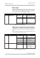
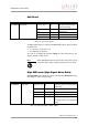
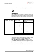
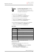
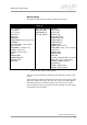
Table Of Contents
- Introduction
- Declarations of conformity
- Safety instructions
- PIKE types and highlights
- FireWire
- Overview
- FireWire in detail
- Serial bus
- FireWire connection capabilities
- Capabilities of 1394a (FireWire 400)
- Capabilities of 1394b (FireWire 800)
- Compatibility between 1394a and 1394b
- Image transfer via 1394a and 1394b
- 1394b bandwidths
- FireWire Plug & play capabilities
- FireWire hot plug precautions
- Operating system support
- 1394a/b comparison
- System components
- Specifications
- Camera dimensions
- PIKE standard housing (2 x 1394b copper)
- PIKE (1394b: 1 x GOF, 1 x copper)
- Tripod adapter
- Pike W90 (2 x 1394b copper)
- Pike W90 (1394b: 1 x GOF, 1 x copper)
- Pike W90 S90 (2 x 1394b copper)
- Pike W90 S90 (1394b: 1 x GOF, 1 x copper)
- Pike W270 (2 x 1394b copper)
- Pike W270 (1394b: 1 x GOF, 1 x copper)
- Pike W270 S90 (2 x 1394b copper)
- Pike W270 S90 (1394b: 1 x GOF, 1 x copper)
- Cross section: C-Mount (VGA size filter)
- Cross section: C-Mount (large filter)
- Adjustment of C-Mount
- F-Mount, K-Mount, M39-Mount
- Camera interfaces
- Description of the data path
- Block diagrams of the cameras
- Sensor
- Channel balance
- White balance
- Auto shutter
- Auto gain
- Manual gain
- Brightness (black level or offset)
- Horizontal mirror function
- Shading correction
- Look-up table (LUT) and gamma function
- Binning (b/w models)
- Sub-sampling
- High SNR mode (High Signal Noise Ratio)
- Frame memory and deferred image transport
- Color interpolation (BAYER demosaicing)
- Sharpness
- Hue and saturation
- Color correction
- Color conversion (RGB ‡ YUV)
- Bulk Trigger
- Level Trigger
- Serial interface
- Controlling image capture
- Video formats, modes and bandwidth
- How does bandwidth affect the frame rate?
- Configuration of the camera
- Camera_Status_Register
- Configuration ROM
- Implemented registers
- Camera initialize register
- Inquiry register for video format
- Inquiry register for video mode
- Inquiry register for video frame rate and base address
- Inquiry register for basic function
- Inquiry register for feature presence
- Inquiry register for feature elements
- Inquiry register for absolute value CSR offset address
- Status and control register for feature
- Feature control error status register
- Video mode control and status registers for Format_7
- Advanced features
- Version information inquiry
- Advanced feature inquiry
- Camera status
- Maximum resolution
- Time base
- Extended shutter
- Test images
- Look-up tables (LUT)
- Shading correction
- Deferred image transport
- Frame information
- Input/output pin control
- Delayed Integration enable
- Auto shutter control
- Auto gain control
- Autofunction AOI
- Color correction
- Trigger delay
- Mirror image
- AFE channel compensation (channel balance)
- Soft Reset
- High SNR mode (High Signal Noise Ratio)
- User profiles
- GPDATA_BUFFER
- Firmware update
- Glossary
- Index

Glossary
PIKE Technical Manual V3.1.0
250
BAYER Patent of Dr. Bryce E. Bayer of Eastman Kodak. This patent refers to a par-
ticular arrangement of color filters used in most single-chip digital image
sensors used in digital cameras to create a color image. The filter pattern
is 50% green, 25% red and 25% blue, hence is also called RGBG or GRGB
BAYER demosaicing BAYER demosaicing is the process of transforming the BAYER mosaic back
to RGB.
BAYER filter see BAYER mosaic
BAYER mosaic A Bayer filter mosaic is a color filter array (CFA) for arranging RGB color
filters on a square grid of photo sensors. The term derives from the name
of its inventor, Bryce Bayer of Eastman Kodak, and refers to a particular
arrangement of color filters used in most single-chip digital cameras.
Bryce Bayer's patent called the green photo sensors luminance-sensitive
elements and the red and blue ones chrominance-sensitive elements. He
used twice as many green elements as red or blue to mimic the human eye's
greater resolving power with green light. These elements are referred to as
samples and after interpolation become pixels.
The raw output of Bayer-filter cameras is referred to as a Bayer Pattern
image. Since each pixel is filtered to record only one of the three colors,
two-thirds of the color data is missing from each. A demosaicing algorithm
is used to interpolate a set of complete red, green, and blue values for each
point, to make an RGB image. Many different algorithms exist.
Big endian Byte order: big units first (compare: little endian)
Binning Binning is the process of combining neighboring pixels while being read
out from the CCD chip.
Binning factor Binning factor is the number of pixels to be combined on a CCD during bin-
ning. A binning factor of 2x2 means that the pixels in two rows and two
columns (a total of four pixels) are combined for CCD readout.
Bit depth Bit depth is the number of bits that are digitized by the A/D converter.
Bitmap A raster graphics image, digital image, or bitmap, is a data file or structure
representing a generally rectangular grid of pixels, or points of color, on a
computer monitor, paper, or other display device.