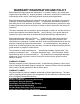
WARRANTY REGISTRATION AND POLICY Buhler Manufacturing products are warranted fo r a period of twelve (12) months from original date of purchase, by original purchaser, to be free fr om defects in material and workmanship under correct, normal agricultural use and proper applications. Buhler Manufacturing’s obligati ons under this warranty shall be limited to the repair or exchange, at Buhler Manufacturing’s option, of any Buhler Manufacturing product or part which proves to be defective as provided.
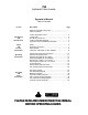
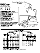
795 Hydraulic Farm Loader Operator’s Manual Table of Contents Section Description Page Warranty Registration and Policy............................................ Table of Contents.................................................................... Introduction and Identification Loader Specification Chart..................................................... 2 Torque Chart .......................................................................... 2 Pre-delivery Check List ...........................
Pre-delivery Check List Before delivering this equipment please complete the following check list. 1. The loader has been installed using the appropriate mounting kit for the tractor and loader. 2. The hydraulic system installed is appropriate for the tractor and loader 3. The loader is properly installed. 4. All bolts are tightened to the torque specifications shown in the torque chart. 5. All safety decals are readable. 6. The loader has been tested and operates properly. 7.
Loader Identification Diagram (HSL Model Shown) For further details refer to Loader Mainframe and Subframe diagrams.
Hydraulic (Hose Kit) Identification Diagrams Hose Kit “A” Loader Powered by the tractor remotes. Consists of four hoses leading from loader tubing to tractor remote couplers Hose Kit “B” Loader operated by an external OC or CC valve that is powered from the tractor remotes Consists of 4 hoses leading from loader tubing to external mounted valve and 2 hoses from valve to tractor couplers. Use the valve type shown with hose kit “B”.
Safety • Never work beneath raised loader unless it is securely supported. The following are instructions for the Lift Lock Supports; • Space rear tires as recommended by tractor manufacturer. Maximize width for high lift applications. • Do not raise bucket to extreme heights while tractor is on an incline. Carry loader low for safety. Note in above illustration how load center moves out when bucket is raised on a slope. Be alert for terrain changes and adjust bucket accordingly.
Important Precautions FALLING HAZARD ELECTROCUTION HAZARD To prevent serious injury or death: To prevent serious injury or death: Do not lift, carry or allow anyone to ride on or work from any portion of loader. Stay away from power lines and cables. Electrocution can occur with or without direct contact.
Safety Decals These decals are located as shown on the Decal Location diagram and the Sub-Frame Assembly diagram. WARNING OVERHEAD HAZARD STAY AWAY FROM UNDER LIFT ARMS AND BUCKET To prevent serious injury or death: 1. Do not stand or work under raised loader, unless supported. 2. Support bucket and lift arms before working under loader. 3. Lower loader to the ground before leaving seat. CAUTION 1. Read Operator's Manual before operating. 2. Move and turn tractor at low speed. 3.
General Instructions and Information As with any piece of equipment, the care with which your loader is operated and maintained will greatly affect it’s life and the safety of the people using it. 1. Keep all pivots well lubricated for longer bushing life. Inspect every 500 hours of operation for wear. 2. Periodically check all bolts for tightness. If any bolt is damaged, replace it with a bolt of equivalent grade or strength. 3.
Operation and Maintenance GENERAL Refer to tractor Operator’s Manual for Operating information on the tractor’s hydraulic system. Hydraulic systems using aux iliary valves should have them located for easy reach from the tractor seat. Hoses should be connected in such a manner that pushing forward on valve handles lowers the boom or dumps the bucket. LOWER BOOM DUMP BUCKET CAUTION: Always connect boom hoses to float section.
Operating Suggestions for Loading DO THIS! When handling heavy loads, be sure to lower lift arms slowly. This is known as feathering the hydraulic lever. If load is lowered too fast and stopped suddenly, excessive shock loads are created which can damage loader or tractor. NOT THIS! When loading bucket, drive straight into material. Attempting to turn tractor while loading bucket can cause damage to both the loader and tractor. A straight bottom offers more resistance to lift.
Operating Suggestions For Backfilling DO THIS! Backgrade work surface with a loaded bucket. Release all pressure on lift cylinders so full weight of bucket is scraping ground. Use heel of bucket. When backfilling approach pile with a flat bucket. Leave dirt in bucket. Dumping on each pass wastes time. NOT THIS! WARNING! DO NOT USE LOADER AS BATTERING RAM! SAFETY: FIRST, LAST, ALWAYS DO NOT use bucket in dumped position for bulldozing.
Attaching the Loader to Your Tractor 1. Position the tractor as centrally as possible and drive, using lowest gear possible, into the loader frame until hoses can be connected. 2. Couple up the hydraulic hose lines to the loader or tractor valve ensuring proper function (see Operator and Maintenance Section) NOTE: When mounting the loader for the first time, slowly work the cylinders back and forth, so that most of the air is removed. Loosen the bolts on the hooks so that they can be moved.
Attaching the Loader to Your Tractor (Continued) 6. When the hook is lined up, dump or roll back the bucket to lower or raise the subframe upright to align with the mounting boot. 7. Continue to drive the tractor forward until the subframe uprights are seated in the boot. 8. Secure the subframe uprights with the bolts and washers. Torque to 500 ft-lbs.
Removing the Loader from Your Tractor WARNING! When removing the loader, it must be fitted with a bucket or other suitable attachment to give the frame stability after removal. If this is not done, the frame will not remain standing. IMPORTANT! Always remove the loader on firm, level ground (away from children’s play areas and high traffic areas). This makes attaching and removing much faster and easier. It also makes the free standing loader more stable. 1.
Removing the Loader from Your Tractor (Continued) 4. Roll back the bucket slightly and simultaneously extend or retract the lift cylinders to free hooks from spools. Then slowly back up the tractor. 5. Once the subframe is clear of the boot and the hook is clear of the mounting boss, roll back the bucket all the way. This raises the rear uprights of the loader. NOTE: On some mountings, the lift cylinders must be extended more while the tractor is backing up, so that the subframes clear the front axle.
Trouble Shooting PROBLEM Loader slow and/or will not dump. POSSlBLE CAUSE Quick couplers leaking. Hydraulic oil too heavy. Oil filter plugged. Hydraulic pump worn. Oil line restricted or leaking. Control valve does not shift properly. Air in hydraulic system. Loader chatters or vibrates when raising and lowering. Excessive movement at pivots Pump noisy Oil leaks. Insufficient lift capacity Cylinder leaks internally. Faulty valve. Air leak in pump inlet line. Air in hydraulic system. Oil level too low.
General Notes and Instructions to the Operator Regarding ALLIED HSL Loader Operations 1. The hydraulic self-leveling system (HSL) utilizes two metering cylinders which displace oil into or out of the bucket cylinders as the loader is raised or lowered. The cylinder volumes and geometry’s are carefully matched for each loader model to provide the correct amount of oil to keep the bucket level after it is initially leveled. 2.
General Notes and Instructions to the Operator Regarding ALLIED TSL Loader Operations 1. The true self levelling system (TSL) utilizes mechanical linkages to maintain bucket level while raising and lowering. The pivot plate weldment, levelling tubes and linkages have been developed to ensure that the bucket remains at the same position throughout its range of motion. This feature is standard with 2.50” and 3.00” diameter bucket cylinders. 2.
Notes 21
795, 795 HSL, S795, S795HSL, 795 TSL, S795 TSL Sub Frame Parts Table Item 1 2 1 2 1 2 1 2 3 4 5 6 7 8 9 10 11 12 13 14 15 16 17 18 19 20 21 22 23 24 25 26 27 Part No.
795 TSL, S795 TSL Main Frame Parts Table Item 1 1 2 3 4 5 6 7 8 9 10 11 12 13 14 15 16 17 18 19 20 21 22 23 24 25 26 27 28 29 30 31 32 33 34 35 36 37 38 39 40 41 42 43 44 45 46 47 48 Part No.
795, S795, 795 HSL, S795 HSL Main Frame Parts Table Item 1 1 1 1 2 3 4 5 6 7 8 9 10 11 12 13 14 15 16 17 18 19 20 21 22 23 24 25 26 27 28 29 Part No.
795, S795 Hydraulic Plumbing Diagram 28
795, S795 Plumbing Parts Table Item 1 2 3 4 5 6 7 8 9 10 11 12 13 14 15 16 17 18 Part No. 24309 24314 811572 811471 811466 812947 112833 112834 112937 112835 112836 112837 812128 811414 812069 11362 81592 81344 Description 3.0 Dia. x 20.75 Cyl. Assy. Bucket 3.0 Dia. x 30.00 Cyl. Assy. Lift 3/8 x 15" Hose 3/4 MORB x 3/4 SWFJIC 3/8 x 20" Hose 3/4 MORB x 3/4 SWFJIC 3/8 x 24" Hose 3/4 MORB x 3/4 SWFJIC 3/8 x 22" Hose 3/4 SWFJIC x 3/4 SWFJIC Tubing - Lift Cyl. Bottom Raise Tubing - Lift Cyl.
795 HSL, S795 HSL Hydraulic Plumbing Diagram 30
795 HSL, S795 HSL Hydraulic Plumbing Diagram Item 1 2 3 4 5 6 7 8 9 10 11 12 13 14 15 16 17 18 19 20 21 22 23 24 25 Part No. 24319 24309 24314 811754 811572 811471 811466 812947 811434 112837 112937 112833 112834 112835 112836 112831 112832 23875 811414 812069 812786 812828 11362 81592 81344 Description 3.5 Dia. x 12.00 Cyl. Assy. Level 3.0 Dia. X 20.75 Cyl. Assy Bucket 3.0 Dia. X 30.00 cyl.
795 TSL, S795 TSL Plumbing Parts Table Item 1 2 3 4 5 6 7 8 9 10 11 12 13 14 15 16 17 18 19 20 21 22 23 24 25 26 Part No. 24314 24708 812069 886897 811414 812128 11362 113031 114233 114234 114235 114236 114328 112837 811471 811424 114605 811434 114237 812697 812696 115260 115730 25253 812052 81922 Description 3.0 DIA x 30.00 Cylinder Assembly Lift 3.0 DIA x 22.
795, S795, 795 HSL, S795 HSL, 795 TSL, S795 TSL Hydraulic Cylinder Assembly Description Diamete r Length of Stroke Retra cted Length Extended Length Cylinder Assembly No. Seal Kit No. Shaft Diameter Item 1 2 3 4 5 6 7 Description Head Plate Shaft Weldment Cylinder Tube Weldment Piston Half (wide) Piston Half (narrow) Self-Locking Nut Shaft Bushing TSL Bucket Bucket Lift Cylinders Cylinders Cylinders 3.00" 3.00” 3.00" 20.75" 22.00” 30.00" 35.38" 51.75” 41.50" 58.13" 73.75” 71.
DIVISION LOCATIONS U.S. WAREHOUSES Allied Division 1201 Regent Ave. W. Box 1003 Winnipeg, MB R2C 3B2 Ph.: (204) 661-8711 Fax: (204) 654-2503 AR, West Memphis (870) 732-3132 NC, Dunn (910) 892-8500 GA, Stone Mountain (770) 908-9439 NC, Statesville (704) 873-0531 IA, Atlantic (712) 243-5520 ND, Bismarck (701) 223-1886 Farm King Division 301 Mountain Street S. Morden, MB R6M 1X7 Ph.