
Technical Manual


Preliminary Release
Alligator Communications Model 2788 Technical Manual REV2.3 Copyright © 2019 Page 10
2.0 Radio Configuration and Operational Check
2.1 General Discussion
Prior to customer installation and electrical connection of the customer’s terminal equipment
to the 2788 radio, it is recommended that the installing technician conduct a brief operational
checkout of the 2788 radio and confirm that all operating parameters are set as desired.
This initial checkout and possible reprogramming/customization is generally performed on the
maintenance shop test bench before the radio is installed and commissioned in a link
application.
The following parts of this section provide guidance in this checkout process and illustrate
alternate configurations and paths to perform the initial checkout.
2.2 Operational Bench Test
To ensure that the 2788 radio is functional prior to installation at the desired site, it is highly
recommended that the following tests be performed in sequence: (Please refer to 2.2.3 Initial
Checkout.)
2.2.1 Antenna Connector
The 2788 radio antenna port (RF Connector) is a coaxial, female, Type N connector. This
connector mates with a male cable connector, Type N such as Amphenol 3900, Andrew L44N,
or MIL Type UG-21. Under most circumstances, bench tests are conducted with a service
monitor (manufactured by IFR Inc., Marconi Instruments Ltd., Hewlett-Packard, Motorola, etc.).
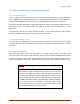
CAUTION
The transmitter should not be keyed on or placed in the transmit
mode without a load connected to the antenna port to prevent
damage to the 2788 radio Power Amplifier due to long periods
(more than 10 minutes) of severely high SWR. An antenna, service
monitor, or dummy load should be attached to the antenna port.
The 2788 radio power output is approximately 2 Watts maximum,
so if a service monitor is connected to the antenna port, ensure
that the service monitor’s input port can handle at least a 5 watt
input to avoid damaging the service monitor.