
Service manual


-0
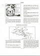
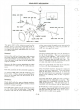
~~> LOCK NUT
·.l~
OPERATING LEVER
BRAKES
Check the lining for wear. It must be re-
placed when worn down to the rivet heads.
Check the brake lever cam for wear. If worn
until adjusting brakes is difficult, either in
the cam surface or hinge points the parts
should be replaced.
Assembly.
Tighten the support plate capscrews to 55 ft.
lbs. torque and the support stud nut to 100ft.
lbs. torque.
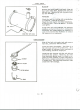
Rivet the lining to the shoe, placing the rivet
head in the lining and upset with special punch
on inner surface of the shoe.
Removal
Remove the wheel and axle housing assembly.
Disconnect the brake pedal return spring and
the brake shoe return springs. The shoes may
Jjow be lifted out. If the lever mechanism is
to be removed, remove the brake support
plate.
The shoes are all alike and may be used in
either front or back. However there is a top
and bottom. The top of the shoe may be iden-
tified by the cutout section in the cam surface.
The lining extends to the lower end of shoe.
There are two holes in the lower end of shoe.
One of the se, the top, is used to attach the
shoe return springs.
BRAKE PEDAL ADJUSTMENT
When new pedals are installed, the pedal
stops must be filed to stop the pedal, approxi-
mately four inches below the seat attaching
pad and to have the pedals level with each
other.
Brake pedal parts should be replaced when
wear makes adjusting brakes difficult.
The pedal lock is on the left hand brake only.
The brakes may be adjusted by loosening the
lock nut on the yoke at the rear end of brake
rod. Raise wheel from floor and remove rod
from pedal and turn into yoke end to tighten
brake. The pedal should have approximately
1-1/2" movement (by hand) before brake is
applied, or a slight drag. Enter the rod in
pedal from the left hand side. The threaded
section of rod will provide enough adjustment
to wear lining downto the rivet heads. Adjust
left brake first. Adjust the right brake until
pedals are level and have equal travel.
G - 29