ALLOY 24-Port Gigabit Web Smart Switch GSS-24T2SFP (24x 10/100/1000Mbps ports + 2 paired SFP Ports) GSS-8T16SFP (8x 10/100/1000Mbps ports + 16 SFP Ports) User’s Manual Version: 1.1.
TABLE OF CONTENT 1 2 Introduction................................................................................................................................. 4 1.1 Managing The Switch ................................................................................................. 6 1.2 Configuration of the Switch ....................................................................................... 7 Configuration .....................................................................................
2.11.3 2.12 ARL Aging ......................................................................................................... 50 User Management ..................................................................................................... 51 2.13 Reset System .............................................................................................................. 52 2.14 Command Line Interface (CLI) .............................................................................. 53 2.14.
1 Introduction The GSS-24T2SFP web smart switch is a high performance web-smart Layer 2 switch that provides users with switched 24 10/100/1000Mbps Ethernet ports, and 2 paired mini-GBIC ports. The mini GBIC ports are paired with ports 1 and 2 on the switch. This pairing is configured to ensure that fibre connections get higher priority over copper if both fibre and copper media exist. Single-mode or multi-mode fiber SFP transceivers can be utilized to provide high speed backbone connectivity.
Main Features Utilizes Latest Broadcom chipset Non-blocking, full-line speed, store-and-forward operation Support normal Ethernet frames and jumbo frames from 64 bytes to 9216 bytes Auto-negotiation and auto-MDIX on all 10/100/1000M copper ports 24x 10/100/1000 RJ-45 ports, 2 ports being shared with SFP mini-GBIC slots Auto-detection for copper/fibre media link on 2 combo ports 512 K bytes packet buffer 8K MAC entries, 4K VLAN entries Web-based interface for s
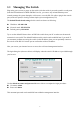
1.1 Managing The Switch Plug-in the power source to power-up the switch. After the switch is powered-on and in a ready state (both the LED indicators POWER and DIAG are lit), you can use any in-band Ethernet port to remotely manage the system through a web browser, or use the RS-232 cable to plug-in the console port (on the rear panel) to locally perform simple system configuration (CLI). The default IP and related settings for this switch are shown as following: IP address: 192.168.0.
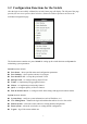
1.2 Configuration Functions for the Switch After the login is successfully validated, the switch’s home page will display. The left part of the page provides function menu options (shown as below). Select one of these options to activate to the individual configuration page. The function menu contains two parts: Switch for setting up the switch functions and System for maintaining system parameters.
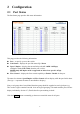
2 Configuration 2.1 Port Status The Port Status page provides link status information. This page provides the following information: Port – to specify a port on the switch Link Status – displays the port link status: Up / Down Speed / Duplex – displays the current link speed (1G / 100M / 10M bps) and duplex mode (Full / Half) when the port is active. NOTE: Only full duplex mode is supported on links whose speed is 1Gbps.
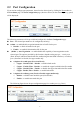
2.2 Port Configuration If you need to configure port parameters, then select the desired port by clicking the Port number in the Port Status page. The Port Configuration page (shown as below) for the selected port (e.g.
Speed / Duplex – to setup the link speed and duplex mode while in forced mode The options for this function can be selected only when the Auto Negotiation is Disabled (in forced mode) for copper media.
2.3 About the Copper/Fiber Media Auto-Detection This switch provides an option to use either copper or fiber media for the first two combo ports Port1 and Port2. This enables port configuration using either copper media or fiber media via use of the mini-GBIC ports and optional SFP (mini-GBIC) modules. The switch will automatically detect the media type that is plugged into the switch and configure the port as required.
2.4 Port Statistics Port Statistics function will let you to see the TX/RX packet counters for each port. Clear Counters button will clear all packet counters to 0. Refresh button will get port statistics again. You can drill down into more detailed port statistics by clicking the Port number.
The table shown below provides a description for each column. UnicastPkts Number of good unicast packets transmitted. MulticastPkts Number of good multicast packets transmitted. BroadcastPkts Number of good broadcast packets transmitted.
2.5 Port-Based VLAN Port-based VLAN divides the switches ports into different Virtual LAN domain groups. After setting up port -based VLAN, ports allocated into different VLAN groups can not access each other. This is like creating virtual switches that do not connect to each other. The VLAN initial setting page is shown as below: Of course, you need to click the Enable/Disable link text to enable/disable port-based VLAN. When port-based VLAN is enabled, the 802.1Q VLAN will be disabled automatically.
Add Port-Based VLAN Groups To add a port-based VLAN group, select the Create New VLAN in VLAN NO dropdown of the Port-Based VLAN page shown as below: After selecting Create New VLAN, the page will change to the following: In the example page, VLAN NO will be auto assigned. The administrator simply needs to set VLAN Port Members. After completing the settings, press the Create button. The screen will then revert back to the VLAN initial settings page.
Below is an example page where the Administrator has set Ports1-12 to VLAN Group2 after clicking the Create button. There now exists a VLAN group No.2 with member Ports1-12. When group No.2 was created, all the members in group No.1 are removed ensure correct operation of the VLAN function.
2.5.1 Delete Port-Based VLAN Groups To delete a port-based VLAN group, just select a desired group (e.g. No.2) to be removed and click the Remove This VLAN button to do the deletion. In this example after selecting the Remove This VLAN button, the resultant is all VLANs deleted, and the Default VLAN 1 - enabled. (see below) Now all ports are set to be members of VLAN group No.1.
2.5.2 Edit Port-Based VLAN Groups To edit the current port-based VLAN group, first select the group (e.g. group No. 3) that you want to edit. To add Port7 & Port8 as members, select these ports and click the Apply button to activate the setting. The following figure shows the latest configuration for the selected group (e.g. No.3).
2.6 802.1Q VLAN IEEE 802.1q (tag-based) VLAN’s can add or strip 802.1q tags based on your parameters set for each transmitting port. Select the 802.1Q VLAN menu to activate the following page where this function can be configured. Currently the switch supports up to 32 tag-based VLAN groups for manual entry. The following pages will described in detail how to configure this feature.
2.6.1 Enable/Disable VLAN In the 802.1Q VLAN page, you can enable/disable the tag-based VLAN function by clicking the (Enable) or (Disable) hyperlink beside the page header: ¾ Enable – to activate the tag-based VLAN function (this will disable the port-based VLAN function). ¾ Disable – to de-activate the tag-based VLAN function. (Any existing tag-based VLAN entries will be retained although tag-based VLAN functions will be disabled. Any retained port-based VLAN entries will auto enable.
2.6.2 802.1Q VLAN Port Configuration Click the Port number to configure the port for 802.1q VLAN. The following figure shows the 802.1Q VLAN Port Configuration page by port. (e.g. Port10) You can select an individual port for configuring the 802.1q settings in the following fields: ¾ ¾ ¾ PVID – enter a valid VLAN ID(1-4094), the PVID must be one of the existing VLAN group ID. UnTag Frame – Accept or drop incoming untagged frames. Tag Frame – Accept or drop incoming tagged frames.
2.6.3 802.1Q VLAN Config The following figure displays the add/delete/edit function for 802.1q VLAN entries. Each VLAN entry has 3 parameters, VID, Tag Members and UnTag Members to be assigned. After selecting the Create New VLAN, the figure shown as below will display: ¾ ¾ VID – a unique VLAN ID, range is from 1 to 4094 Tag Members & UnTag Members – Click the U/T icon to switch between Non Member, Tag Member or Untag Member.
Here is an example on how to configure the 802.1q VLAN. Now there are four existing 802.1q VLAN entries shown as below. Note: You can delete 802.1q VLAN entries via the selecting the Vlan from the dropdown list and (e.g. VID = 200), then click the Remove This VLAN button to perform the deletion. Note the 802.1q VLAN table now shows the following entries: The VID entry (VID=200) is successfully deleted.
If you would like to edit the parameters of an 802.1q VLAN, just select a VID to be changed (e.g. VID =300), then make the required changes and click the Apply button : Port 17 and Port18 are selected to be the tag members of this group.
2.7 Trunking The GSS-24T2SFP web smart switch supports MAC-based trunking. This allows more than one port to be grouped together as a single link connection between two switch devices. This is also useful for switch-to-server and switch-to-router applications. The GSS-24T2SFP web smart switch allows four trunk groups that can accommodate up to eight trunk members in each group. A port in one trunk group cannot be a member of another trunk simultaneously.
2.7.1 Trunking Rules The following rules determine your configuration for port trunking: The attributes of all trunk member ports in Port Configuration, Mirror, Rate Control, 802.1Q VLAN and Port-Based VLAN functions must be the same. All trunk member ports can not be a capture port or monitored port in the Mirror function.
When the enabled trunk group is set to disabled, all trunk member ports will be released to ordinary ports and their functions can be configured individually. At that moment, their configuration attributes will be returned to their previous state. The following 3 figures show that the settings of a port while in a trunk group can be reverted back to normal once not in the trunk group any more.
2.7.2 Get/Refresh the Latest Trunk Settings Click the Trunk menu on the web page, the latest trunk settings on the switch will be displayed.
2.7.3 Enable Trunk ¾ ¾ ¾ Step 1: Choose the Distribution Criterion. Step 2: Choose the member port(s) up to 8 ports for each trunk group. Step 3: Click the Apply button to enable trunk settings.
2.7.4 Modify Trunk Settings ¾ ¾ ¾ Step 1: Choose the Distribution Criterion. Step 2: Choose the member port(s) up to 8 ports for each trunk group. Step 3: Click the Apply button to modify trunk settings.
2.7.5 Disable Trunk ¾ ¾ Step 1: Click the Not Trunking hyperlink (the baseline option) Step 2: Click the Apply button to disable trunking.
2.8 Port Mirroring Port mirroring allows ingress and/or egress traffic to be monitored by a single port. The single port is defined as the mirror capture port. The GSS-24T2SFP web smart switch can be configured to mirror the ingress and/or egress traffics of another port. Port monitoring is independent of L2 switching. Select the Mirror menu on the web page to activate the configuration page.
2.8.1 Get/Refresh the Latest Mirror Settings Click the Mirror menu on the web page, the latest mirror settings on the switch will be displayed. The following parameters can be set: Mirroring Options – There are four options for each port: ¾ Disable Mirror – to disable mirror function. ¾ Mirror All Frames – to set the corresponding port configuration to monitor bi-directional traffic.
2.8.2 Enable Mirror ¾ ¾ ¾ ¾ Step 1: Choose the Mirror option as Mirror All Frames. Step 2: Choose the Monitored Port (ie Port16) Step 3: Choose the Capture Port (ie Port8) Step 4: Click the Apply button to enable the mirroring settings.
2.8.3 Modify Mirror Settings ¾ ¾ ¾ ¾ Step 1: Change the Mirror option as Mirror Outgoing Frames. Step 2: Change the Monitored Port to be Port3 Step 3: Change the Capture Port to be Port22. Step 4: Click the Apply button to modify the mirroring settings.
2.8.4 Disable Mirror ¾ ¾ Step 1: Choose the Mirror option as Disable Mirror. Step 2: Click the Apply button to disable mirroring.
2.9 QOS (Quality of Service) The 24G web smart switch provides up to four internal transmit queues per port to support four different traffic priorities. High-priority traffic experiences less delay in the switch than that of lower priority traffic under congested conditions. This can be critical for congestion sensitive traffic such as VOIP. The GSS-24T2SFP web smart switch provides three types of QOS. It can assign packets to one of four transmit queues according to 802.1P QOS.
2.9.1 Get/Refresh the Latest QOS Settings Click the QOS menu on the web page, the latest QOS settings on the switch will be displayed. The following parameters can be configured: Scheduling Method ¾ Strict Priority – Sets the switch to transmit packets with Strict Priority algorithm ¾ Weighted Round Robin – Set the switch to transmit packets based on a Weighted Round Robin algorithm Priority/Queue Map ¾ To set the Priority and Queue map. Weight ¾ To set the weight for every transmit queue.
2.9.2 Enable QOS ¾ ¾ ¾ ¾ Step 1: Choose the Scheduling Method (ie: Weighted Round Robin). Step 2: Set Priority/Queue map (ie: Priority1, 2, 3 and 4 belong to Queue0, Priority4 and 5 belong to Queue1, Priority6 belongs to Queue2, Priority7 belongs to Queue4). Step 3: If the scheduling method is Weighted Round Robin, assign a weight for every transmit queue (ex: Queue0 weight = 1, Queue1 weight = 3, Queue2 weight = 5, Queue3 weight = 7). Step 4: Click the Apply button to enable the QOS settings.
2.9.3 Modify QOS Settings ¾ ¾ Step 1: Change the Scheduling Method to be Strict Priority. Step 2: Change the Priority/Queue map (ie: Prirotiy0 belongs to Queue3, Priority1, 2 and 3 belong to Queue2, Priority4, 5 and 6 belong to Queue1, and Priority7 belongs to Queue0). ¾ Step 3: Click the Apply button to modify the QOS settings.
2.10 Rate and Storm Control To improve overall system performance, the GSS-24T2SFP web smart switch provides rate and broadcast storm control. This can limit the per-port traffic rate and limit global broadcast storms from reducing the performance of the overall system. 2.10.1 Rate Control The switch supports per-port rate control. When the incoming frame rate of a particular port exceeds a selected rate, the excess frame traffic is subject to flow control through either packet droping or flow control.
Select the port number to setup the per-port rate control value. In this page an ingress rate limit dropdown is shown as in the following figure, select one of 14 different rates to limit the rate or select “No Limit” to allow un-limited data rates for this port. After clicking the Apply button to activate the setting, the previous page will be displayed and the latest settings activated.
2.10.2 Storm Control In the Rate Limit and Storm Control page, the hyperlink (e.g. Disabled) on the row labeled Storm Control, shows the current setting for this function. Enabling or Disabling this function will globally affect to all ports in the system. Click the hyperlink to configure. In the Storm Control page, there are 2 fields to configure: Storm Control Type – 5 options are provided in this dropdown ¾ Disabled – to disable storm control.
Storm Control Rate – this field provides 13 different control rates from 1fps (frames per second) to 15,000fps. This dropdown will be disabled while the Storm Control Type is disabled. After selecting the storm control type and rate, click the Apply button to activate the settings for this function. The figure shown as below is an example of storm control configuration with a type selection of “broadcast only” and a limited rate of 15fps.
2.11 System Setup System Setup page provides management information for the switch. The page shown below can be activated by clicking on the System Setup menu under the System section.
2.11.1 Firmware Update The GSS-24T2SFP web smart switch provides a firmware update feature, customized requests and system fault recovery. The page for this is shown below can be activated by clicking the Update link in System Setup page. GSS-24T2SFP This system supports both BOOTP/TFTP and TFTP to update the firmware. The TFTP server IP address and firmware filename needs to be correctly provided to the switch to start the firmware updating if the TFTP method is selected.
Firmware Update Via TFTP To perform the firmware update process, it is necessary to correctly prepare a TFTP server and the firmware file which will be uploaded to the switch by the TFTP server. (Please refer to the TFTP software vendor’s instruction guide for setting up the TFTP server) When the TFTP server and the firmware file are ready, enter the TFTP server IP address and firmware filename. Click the Apply button to start the firmware update through any RJ-45 port on the switch.
2.11.1.1 Firmware Update Via BOOTP/TFTP Before performing the firmware update, please correctly prepare a BOOTP/TFTP server and the firmware file which will be uploaded to the switch by the TFTP server. (Please refer to the TFTP software vendor’s instruction guide for setting up the TFTP server). When the BOOTP/TFTP server and the firmware file are ready, click the Apply button to start the firmware update through the any RJ-45 port on the switch.
2.11.2 DHCP Client The IP address of the GSS-24T2SFP web smart switch can be statically assigned by the system administrator or dynamically assigned by a DHCP server. 2.11.2.1 Assign a fixed IP address Change DHCP Client to be disabled. Enter a fixed IP address, Subnet mask and Gateway, and then click the Apply button. 2.11.2.2 Assign an IP address by DHCP server Change DHCP Client to be enabled.
2.11.3 ARL Aging The GSS-24T2SFP web smart switch supports an auto aging timer for MAC address entries in address table. If ARL aging is enabled and aging time is 300 seconds, every MAC address entry learned from every front port will keep in the address table for 300 seconds. After 300 seconds, the switch will remove the MAC entry. Click ARL Aging to modify aging time settings. Check Enable ARL Aging checkbox to enable it. Uncheck Enable ARL Aging to disable it.
2.12 User Management The User management screen is used to maintain the username and password for login validation to access to the switch. The switch provides only one login account for configuration management. Click the User Management menu to activate the User Management page shown as below: New Username – to set the username string (max. 10 characters) New Password – to set the password string (max.
2.13 Reset System The switch can be rebooted or factory defaulted via the following methods. Click Reboot System menu to reboot the switch. Click Reset System menu to reset the switch to its factory default settings. ¾ Reboot System –Reboot the system. All configuration settings will be retained. If you want to keep all your configurations then select this option.
2.14 Command Line Interface (CLI) In addition to the web management interface, the GSS-24T2SFP web smart switch also provides a serial interface (RS-232) as a console port on the rear panel to manage the switch. A Windows Hyper Terminal session is recommended for use. This section will explain how to setup and use Hyper Terminal to manage this switch. 2.14.1 Hyper Terminal Setup Options Baud Rate: 19200 bps Data Bits: 8 Parity: None Stop bits: 1 Flow control: None 2.14.
Help Menu Press “H”, “h” or “?” to show all management commands in console. Get System Information Press “IG” or “ig” to show model name and firmware version. Get Current Network Settings Press “NG” or “ng” to show DHCP client status, system IP address, network mask, gateway and MAC address.
Configure Network Press “NS” or “ns” to configure system network. If the Administrator wants to assign the switch an IP address by DHCP server, then enter “Y” or “y” to start DHCP process. If the Administrator wants to assign the switch a fixed IP address, then enter “N” or “n” to abort DHCP progress. User Management Press “UM” or “um” to configure the admin account and password which is used to login the switch. Enter new username and password.
Upgrade Firmware Via TFTP or BOOTP/TFTP Press “UF” or “uf” to start firmware upgrade progress via TFTP server. Choose “1” to update firmware via TFTP. Enter TFTP server IP address and firmware filename. Choose “2” to update firmware via BOOTP/TFTP. After the GSS-24T2SFP firmware upgrade process is finished. Press “IG” or “ig” to check firmware version after login. Reboot System Press “RB” or “rb” to restart this system.
Reboot System After Write Default Press “RD” or “rd” to reset the switch to factory default settings. Logout Press “LO” or “lo” to logout system.
3 Specifications Standards Compliance IEEE 802.3 10BaseT Ethernet IEEE 802.3u 100BaseTX Fast Ethernet IEEE 802.3ab 1000Base Gigabit Ethernet IEEE 802.3x flow control both on half and full duplex IEEE 802.
Power Input: 100-240VAC, 50/60Hz Power consumption: 40 Watts max. Dimensions 440mm (W) × 184mm (D) × 44mm (H) Weight 2.