POE120 Series 10/100 Base-TX to 100Base-FX Converter POE Powered Device Version 1.
1. Overview The POE120 Series IEEE 802.3u compliant media converters support two types of media 10/100 Base-TX and 100Base-FX. With LFP (Link Fault Propagation) support it allows the administrator to easily diagnose link faults on their network. If the Copper or Fibre link fails, the converter forces the link status of the connecting device to also fail. The POE120 Series media converters are fully compliant to the IEEE 802.3af standard.
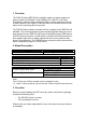
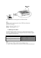
4. Installing the Converter 4.1 POE120 converter connected to a Power Sourcing Equipment Device (PSE) 1. Connect the copper cable to your IEEE 802.3af compliant PSE device. The POE120 can also work as a standard media converter and connect to a non POE device. (power supply is optional) 2. Connect the fibre cable to your connecting device. Note: - Please make sure that the 802.3af power is being supplied from a PSE device to the PD Media Converter. - In case there is no 802.
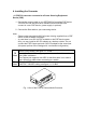
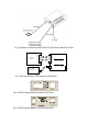
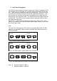
Fig. 2 Example connection between POE120, PSE device and Fibre Cable 100FX Fibre Network RX TX TX RX POE120 Series Media Converter AC PoE PSE or PoE Injector Fig. 3 POE120 Series to PSE Device or POE Injector POE1 20 Series 10/ 100 Base- TX to 100Base- FX Fig. 4 POE120 Series Media Converter Front Panel Fig.
Fig. 6 Pairs used for receiving power over Ethernet Cable. Note: The pins used for receiving power from a PSE Device follows the IEEE 802.3af standard. Endpoint: -48V via TP pins 1, 2, 3, 6 Midspan: - 48V via pins 4, 5, 7, 8 5. WDM Single Fibre Model The POE120 Series media converter has an optional Wavelength Division Multiplexing (WDM) Model that can transport bi-directional full duplex signals over a single fibre simultaneously.
. Link Failure Propagation The POE120 Series media converters support Link Failure Propagation (LFP). If the Copper port is unplugged, the converter stops transmission on the fibre port. This causes the remote fibre node link to fail as well. The LED’s on the converter will now show link failure on both the copper and fibre ports. If the fibre link fails, the converter restarts auto-negotiation on the copper port but always stays in the link failure state.
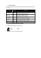
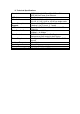
. LED Description The following table describes the LED’s located on the POE100 Series media converter.
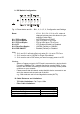
9. DIP Switch Configuration Fig. 11 Reset button and S1 – Bit 1, 2, 3, 4, 5, 6, Configuration and Settings Reset S1-1 TP Port Mode S1-2 TP Port Speed S1-3 TP Port Duplex S1-4 LFP S1-5 Fibre Port Duplex S1-6 POE ON/OFF : If S1-1, S1-2, S1-3, S1-4 or S1- status is changed, please press this button for your settings to take effect.
11. Technical Specifications IEEE 802.3u 10/100Base-TX, 100Base-FX IEEE 802.3af Power Over Ethernet Cat. 5 cable up to 100m UTP Cable: 50/125, 62.5/125 or 100/140 µm multi mode Fibre Cable: 8.3/125, 8.7/125, 9/125 or 10/125 µm single mode “Endpoint” Via TP Pins 1, 2, 3 and 6 Power Reception ”Midspan” Via TP pins 4, 5, 7 and 8 Support: Power, POE, TP LNK/ACT, 100, FX LNK/ACT, LED Indicators: FDX/COL 100Mbbps – 148,800pps Data Transfer Rate: 10Mbps – 14,880pps IEEE 802.