APS Series Gigabit Managed PoE+ Switches APS-10T2SFP APS-26T6SFP APS-48T4SFP APS-24T4S4SP APS-48T4S4SP Quick Install Guide Version: 1.0.
AMS Quick Install Guide About this Guide ............................................................................................................................................ 3 Compliances and Safety Statements.............................................................................................................. 4 1. Introduction ............................................................................................................
AMS Quick Install Guide 8. Power and Cooling Problems....................................................................................... 28 Installation ................................................................................................................................................... 28 In-band Access ............................................................................................................................................. 28 9. Specifications..........................
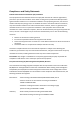
AMS Quick Install Guide About this Guide Purpose This guide gives specific information on how to operate and use the management functions of the switch. Audience The guide is intended for use by network administrators who are responsible for operating and maintaining network equipment; consequently, it assumes a basic working knowledge of general switch functions, the Internet Protocol (IP), and Simple Network Management Protocol (SNMP). Warranty The APS series comes with a standard 3 year warranty.
AMS Quick Install Guide Compliances and Safety Statements Federal Communications Commission (FCC) Statement This equipment has been tested and found to comply with the limits for a Class A digital device, pursuant to part 15 of the FCC Rules. These limits are designed to provide reasonable protection against harmful interference in a residential installation.
AMS Quick Install Guide - Radio-frequency electromagnetic field according to IEC 61000-43:2006+A1:2007+A2:2010 - Electrical fast trsnsient/burst according to IEC 61000-4-4:2010 - Surge immunity test according to IEC 61000-4-5:2005 - Immunity to conducted disturbances, Induced by radio-frequency fields:IEC 61000-4-6:2008 - Power frequency magnetic field immunity test according to IEC 61000-4-8:2009 - Voltage dips, short interruptions and voltage variations immunity test according to IEC 61000-4-11:2004 LVD:
AMS Quick Install Guide SAFETY PRECAUTIONS Read the following information carefully before operating the device. Please follow the following precaution items to protect the device from risks and damage caused by fire and electric power: Use the power adapter that is included with the device package. Pay attention to the power load of the outlet or prolonged lines. An overburdened power outlet or damaged cords and plugs may cause electric shock or fire.
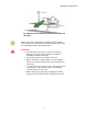
AMS Quick Install Guide Fig. Additional arrester installed between outdoor device and this switch NOTE: The switch is indoor device; if it will be used in outdoor environment or connects with some outdoor device, then it must use a lightning arrester to protect the switch WARNING: Self-demolition of Product is strictly prohibited. Damage caused by self-demolition will result in voiding the switches warranty. Do not place product in outdoor locations.
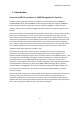
AMS Quick Install Guide 1. Introduction Overview of APS Series Layer 2+ SNMP Managed PoE+ Switches APS Series switch models offer flexible port configurations, with combinations of 1000Base-T 10/100/1000mbps RJ-45, paired 1000Base-T/SFP arrays (with the SFP slot supporting 100Mbps or 1Gbps mini-GBIC modules), unpaired SFP slots (also supporting 100Mbps or 1Gbps mini-GBIC modules), and SFP+ slots for 1Gbps or 10Gbps mini-GBIC modules. Port densities range from 10 to 48 ports.
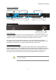
AMS Quick Install Guide Front View of APS-24T6SFP Power LED Reset Console TP Port LED’s SFP Port LED’s 10/100/1000Base-T RJ-45 Ports 100/1G Combo SFP Ports Rear View of APS-24T6SFP IEC Power Socket Switch Architecture The switch performs at wire-speed, non-blocking switching fabric. This allows wire-speed transport of multiple packets at low latency on all ports simultaneously. The switch also features full-duplex capability on all ports, which effectively doubles the bandwidth of each connection.
AMS Quick Install Guide 2. Description of Hardware 1000Base-T Ports The APS Series switches contain 4x 1000BASE-T RJ-45 ports (APS-4T24S4SFP), 24x 1000BASE-T RJ-45 ports (APS-24T6SFP & APS-24T4S4SFP) or 48x 1000BASE-T RJ-45 ports (APS-48T4SFP & APS48T4S4SFP). All RJ-45 ports support automatic MDI/MDI-X operation, auto-negotiation and IEEE 802.3x auto-negotiation of flow control, so the optimum data rate and transmission can be selected automatically.
AMS Quick Install Guide MGBIC-SLC120 9/125 1550 120Km MGBICWDMS3.02 1G N/A TX-1310/RX-1550 2Km MGBICWDMS5.02 1G N/A TX-1550/RX-1310 2Km MGBICWDMS3.20 1G N/A TX-1310/RX-1550 20Km MGBICWDMS5.20 1G N/A TX-1550/RX-1310 20Km MGBICWDMS3.40 1G N/A TX-1310/RX-1550 40Km MGBICWDMS5.40 1G N/A TX-1550/RX-1310 40Km MGBICWDMS3.80 1G N/A TX-1310/RX-1550 80Km MGBICWDMS5.80 1G N/A TX-1550/RX-1310 80Km 100SFP-M02 100M 62.
AMS Quick Install Guide Port and System Status LED’s The APS Series switches include a display panel for system and port indications that simplify installation and network troubleshooting. The LEDs are located on left hand side of the front panel or over the port sockets for easy viewing. Details are shown below and described in the following tables.
AMS Quick Install Guide 3. Network Planning Installing the Switch Selecting a site The APS Series switches can be rack mounted in a standard 19” equipment rack using the supplied Rack Mount Kit, or they can be installed on any flat surface. Be sure to follow the guidelines below when choosing a location. The site should be: At the centre of all the devices you want to link and near a power outlet.
AMS Quick Install Guide Ethernet Cabling To ensure proper operation when installing the switch into a network, make sure that the current cables are suitable for 100BASE-TX or 1000BASE-T operation.
AMS Quick Install Guide WARNING: The mini-GBICs are Class 1 laser devices. Avoid direct eye exposure to the beam coming from the transmit port. Mounting The switch can be mounted in a standard 19-inch equipment rack or on a desktop or shelf. Mounting instructions for each type of installation type is as follows.
AMS Quick Install Guide 2. Mount the device in the rack using four rack-mounting screws (not provided). Be sure to secure the lower rack-mounting screws first to prevent the brackets from being bent by the weight of the switch. 3. If installing a single switch, turn to “Connecting to a Power Source” at the end of this chapter. 4. If installing multiple switches, please follow steps 1 and 2 for installation of the other switches. Desktop Mounting 1.
AMS Quick Install Guide Installing an optional SFP Module All SFP Modules are hot swappable and can be interchanged without having to power off the switch. NOTE: Depending on the model being used the SFP slots are shared with 10/100/1000Base-T RJ-45 ports. If a SFP is installed in a slot, the associated RJ-45 port is disabled and cannot be used. The SFP ports operate only at full duplex. Half duplex operation is not supported.
AMS Quick Install Guide Connecting to a power source To switch the power off, please remove the power cord from the switch. To turn the power on, please insert the power cable into the switch. Inserting the power cord to switch and AC power socket 1. Insert the power cable plug directly into the AC Socket located at the back of the switch. 2. Plug the other end of the cable into a grounded, 3-Pin, AC power source. 3. Check the front-panel LEDs as the device is powered on to be sure the POWER LED is lit.
AMS Quick Install Guide Switch’s 8-Pin Serial Port Null Modem PC’s 9-Pin DTE Port 2 RXD (receive data) ----------------- 3 TXD (transmit data) 3 RXD (receive data) ----------------- 2 RXD (receive data) 5 SGND (Signal ground) ------------------- 5 SGND (Signal ground) NOTE: No other pins are used.
AMS Quick Install Guide 4. Operation of Web-based Management The default values of the APS Series switches are listed in the table below: IP Address Subnet Mask 192.168.1.1 255.255.255.0 Default Gateway 192.168.1.254 Username admin Password To access the web management of an APS Series switch enter the default IP Address in web browser and hit enter. E.g http://192.168.1.
AMS Quick Install Guide 5. Making Network Connections Connecting Network Devices The APS Series switches are designed to be connected to 10, 100 or 1000Mbps network cards in PCs and servers, as well as to other switches and hubs. It may also be connected to remote devices using optional SFP transceivers. Twisted-Pair Guidelines Each device requires an unshielded twisted-pair (UTP) or shielded twisted-pair (STP) cable with RJ-45 connectors at both ends.
AMS Quick Install Guide Connecting to PC’s, Servers and Switches 1. Attach one end of a twisted-pair cable segment to the device’s RJ-45 connector. 2. If the device is a network card and the switch is in the wiring closet, attach the other end of the cable segment to a modular wall outlet that is connected to the wiring closet. (See the section “Network Wiring Connections.”) Otherwise, attach the other end to an available port on the switch. 3.
AMS Quick Install Guide Network Wiring Connections Today, the punch-down block is an integral part of many of the newer equipment racks. It is actually part of the patch panel. Instructions for making connections in the wiring closet with this type of equipment follows. 1. Attach one end of a patch cable to an available port on the switch, and the other end to the patch panel. 2.
AMS Quick Install Guide Fibre Optic SFP Devices An optional Gigabit SFP transceiver can be used for a backbone connection between switches, or for connecting to a high-speed server. Each single-mode fibre port requires 9/125 micron single-mode fibre optic cable with an LC connector at both ends. Each multimode fibre optic port requires 50/125 or 62.5/125 micron multimode fibre optic cabling with an LC connector at both ends. WARNING: This switch uses lasers to transmit signals over fibre optic cable.
AMS Quick Install Guide 6. Cable Labeling and Connection Records When planning a network installation, it is essential to label the opposing ends of cables and to record where each cable is connected. This will allow users to easily locate inter-connected devices, isolate faults and change your topology without need for unnecessary time consumption. To best manage the physical implementations of your network, follow these guidelines: Clearly label the opposing ends of each cable.
AMS Quick Install Guide 7. Troubleshooting Basic Troubleshooting Tips Most problems are caused by the following situations. Check for these items first when starting your troubleshooting: Connecting to devices that have a fixed full- duplex configuration. The RJ-45 ports are configured as “Auto”.
AMS Quick Install Guide Check the port configuration. A port on your Switch may not be operating as you expect because it has been put into a “blocking” state by Spanning Tree, GVRP (automatic VLANs), or LACP (automatic trunking). (Note that the normal operation of the Spanning Tree, GVRP, and LACP features may put the port in a blocking state.) Or, the port just may have been configured as disabled through software.
AMS Quick Install Guide 8. Power and Cooling Problems Installation If the power indicator does not turn on when the power cord is plugged in, you may have a problem with the power outlet, power cord, or internal power supply. However, if the unit powers off after running for a while, check for loose power connections, power losses or surges at the power outlet. If you still cannot isolate the problem, the internal power supply may be defective.
AMS Quick Install Guide 9. Specifications APS Series Model 10T2SFP 24T6SFP 48T4SFP 24T4S4SFP 48T4S4SFP Interface Total Ports, comprising 10x GbE 26x GbE 48x GbE 28x GbE 52x GbE UTP (10/100/1000Mbps) 8 20 44 20 44 UTP/(100M/1G) SFP 2 4 4 4 4 SFP (100M/1G) - 2 - - - SFP+ (1G/10G) - - - 4 4 8 24 48 24 48 UTP Ports 1-8 UTP Ports 1-24 UTP Ports 1-48 UTP Ports 124 UTP Ports 148 Power Over Ethernet Total IEEE 802.
AMS Quick Install Guide per group VLAN Voice VLAN group IGMP Snooping group group 4K VLAN’s: Port based VLAN’s; 802.1Q; MAC Based VLAN’s; Management VLAN; Private VLAN Voice traffic is automatically assigned to a voice-specific VLAN and treated with appropriate levels of QoS GVRP DHCP Relay per group Supported Relay of DHCP traffic to DHCP server in different VLAN. Works with DHCP Option 82 V1, V2 and v3 .
AMS Quick Install Guide packets, TCP flag. Port Security Locks MAC Addresses to ports, and limits the number of learned MAC addresses Quality of Service H/W Priority Queue Scheduling Supports 8 hardware priority queues Strict priority and weighted round-robin (WRR). Queue assignment based on DSCP and class of service (802.1p/ CoS) Classification Port based; 802.
AMS Quick Install Guide when the switch detects link up. Cable length detection Adjusts the signal strength based on the cable length. Reduces the power consumption for shorter cables. Discovery LLDP IEEE802.1AB - Link Layer Detection Protocol with LLDP-MED extensions Environmental Specifications Dimensions (WxHxD, mm) 280 x 44 x 166 Case Desktop Weight 1.382Kg Temperature Humidity 442 x 44 x 300 442 x 44 x 385 1RU rackmount (mounting kit included), all metal case 3.