ALLOY 8-Port Gigabit Web Smart Switch (GSS-8T2SFP) User’s Manual Version: 1.0.
TABLE OF CONTENT 1. 2 Introduction................................................................................................................................. 4 1.1 Main Features.............................................................................................................. 5 1.2 Initial Setup ................................................................................................................. 6 1.3 Main Configuration Functions ...............................................
2.9.2 2.9.3 3 Ingress Rate Control Common Config............................................................ 45 Ingress Rate Limit Config for Buckets............................................................ 46 2.10 Address Management ............................................................................................... 48 2.10.1 Get/Refresh the Latest Address Management Settings ................................. 49 2.10.2 Add a New Entry ........................................................
1. Introduction The GSS-8T2SFP is a high performance web-smart switch that provides up to 8 10/100/1000Mbps copper Ethernet ports and 2 mini-GBIC ports. The versatility of this switch allows users to migrate easily from existing Ethernet or Fast Ethernet networks while providing an easy upgrade path to a Gigabit Ethernet network. It also provides users with a simple management interface via an out-of-band Ethernet port rather than a sophisticated SNMP management structure.
1.1 Main Features This switch provides the following main features: n Non-blocking, full- line speed, store-and-forward n Jumbo frame support, Max. packet length 9728 bytes n Auto-Negotiation and Auto-MDIX on all 10/100/1000M copper ports n Up to 8x 10/100/1000 RJ-45 copper ports and 2 mini- GBIC ports with optional fibre transceivers. n Automatic media detection is provided for the last two shared ports for copper/fibre connectio n. n 1.
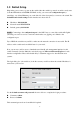
1.2 Initial Setup Plug- in the power source to power-up the switch. After the switch is powered-on and in a ready state (both the LED indicators POWER and DIAG are lit), you can use the configuration port (a standalone, out-of-band Ethernet port on the left side of the front panel) to connect to the switch. The default IP and related settings for this interface are shown below: n n n IP address: 192.168.0.100 Network mask: 255.255.255.0 Default gateway:192.168.0.
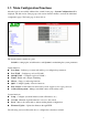
1.3 Main Configuration Functions After the login is successfully validated, the switch’s home page – System Configuration will be displayed. The left section of the page provides various function menus to activate the individual configuration page s. The home page is shown below: The function menu contains two parts: Switch for setting up the switch functions and System for maintaining the system parameters.
2 Configuration 2.1 Port Status This page provides the current link status for all 8 ports. This page provides the following information: n Port No. – The specific port on the switch n Link Status – Show the port link status : Up / Down / Disable Ø Up – port link is up. Ø Down – port link is down. Ø Disable – Traffic will be blocked while the link status is up and the port’s Status option is “Disable” in Port Configuration page.
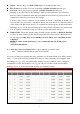
n n n n Duplex – Indicates the port as Full or Half duplex mode while the link is up. Flow Control –Shows the flow control capability as Enabled / Disabled for this port. Protected – Shows the protected capability as Enabled / Disabled for this port. Defining a port as Protected, is like defining a simple port based VLAN. A port selected as Protected, cannot communicate with other ports that have been selected as protected, but can communicate with non protected ports. For example.
Port Configuration If you need to edit the port configuration, select one of the desired ports by clicking its radio button in the Select column of the Port Status page. The Configure button will be enabled when any port is selected. Click the Configure button to enter the Port Configuration page (shown below) for the selected port (e.g.
n n n Flow Control Ø Enable – Enable flow control for this port Ø Disable -- Disable flow control for this port Protected Port Ø Enable – to enable this function for the port (to be a protected port) Ø Disable -- to disable this function for the port (to be an unprotected port) Jumbo Frame Support Ø Enable – Enable Jumbo frames Ø Disable – Disable Jumbo frames After the desired options have been selected for the above functions, click the Submit button to save the current settings to the switch and reve
2.3 Port-Based VLAN Port-based VLAN segregates ports into various groups. Once you define Port Based VLAN groups only ports that are members of the same VLAN group can communicate with each other. Broadcast, Multicast and Unicast packets are limited to within their respective ports VLAN group. The initial VLAN setting page is shown below: You can add, delete, and modify the port-based VLAN’s based on your particular requirements. The switch supports up to 8 port-based VLAN groups for manual entry.
2.3.1 Add Port-Based VLAN Groups To add a port-based VLAN group, click the Add button in Port-Based VLAN page, the following web page will be shown: (if the default entry had previously been removed): The VLAN NO is automatically configured to the next available. The switch administrator needs to add the VLAN Port Members. After you have completed your configuration, press the Submit button you will then be redirected back to the VLAN initial set up page.
2.3.2 Delete Port-Based VLAN Groups To delete a port-based VLAN group, just select the desired group to be removed and click the Delete button. As shown in the figure above, there are 2 port-based VLAN groups 1 and 2. Check the radio button at the head of each row and press the Delete Button. The result is shown in the following figure. The port-based VLAN Group 1 and it’s members P1, P2, P3, P4 have now been deleted. The port-based VLAN Group2 now becomes VLAN Group1.
2.3.3 Edit Port-Based VLAN Groups To edit the current port-based VLAN group, first check the radio button of the group you want to edit and click the Edit button. Then set the member Ports 7 and 8 Press the Submit button to complete the Edit function. The port-based VLAN Group Member changes to Port 7 and 8 from Port 5, 6, 7 and 8.
2.4 802.1Q VLAN IEEE 802.1Q (tag-based) VLAN operates by reading/writing 802.1Q tags depending on the requirements of the individual transmitting port. To configure this type of VLAN, Click on the 802.1Q VLAN menu. This page provides the following functions to configure the 802.1Q VLAN: n n n n Enable / Disable VLAN Frames which VID’s are not in the VLAN table 802.1Q control per port configuration 802.
2.4.1 Enable/Disable VLAN In the 802.1Q VLAN page, there are two options provided to enable /disable tag-based VLAN functions: Ø Enable – Activate tag-based VLAN functions. If any tag-based VLAN entry is created. Ø Disable – De-activate tag-based VLAN functions, even if there are some VLAN entries created. (i.e. Tag-based VLAN entries are retained even though the tag-based VLAN function is disabled.) Remember to click the Apply button to activate and save the settings to the switch. 2.4.
2.4.3 802.1Q Control Per Port Config The above screen allows you to control individual port 802.1Q settings: Ø Port No – Select the port to be configured. Only the red-colored leading port will been shown in the dropdown if a trunk group has been created. Ø Tag Config – There are two parameters in this field: Priority (0-7) and VID (1-4094). Set the 2 parameters to determine the 802.1Q tag contents. Ø Non 1Q Frame – This determines what will occur to packets that do not match the 802.
2.4.4 802.1Q VLAN Table Config The following screen capture shows the page used to add/delete/edit the 802.1Q VLAN entry. Each VLAN entry has 3 parameters, VID, Members and UnTag Members . After clicking the Add button, the figure shown below will be displayed: Ø Ø Ø VID – a unique VLAN ID, range is from 1 to 4094 Members – the port members in an 802.1Q VLAN group. UnTag Members – When you specified the 802.
Here is an example showing how to configure the 802.1Q VLAN Table Config parameters. There are four existing 802.1Q VLAN entries as shown below. To delete the 802.1Q VLAN entry, click a radio button on the Select column (e.g. Entry No.2, VID = 285), then click the Delete button to do perform the deletion. Once the above has been completed, the 802.1Q VLAN table will be changed accordingly: The VID entry (No.2, VID=285) has been successfully deleted.
If you would like to edit the parameters of an 802.1Q VLAN entry, select the entry that you require changed (e.g. entry No.2, VID = 3) then click the Edit button to perform the modifications: VID is changed to 333 and port 1 and port 8 are selected to be members of this group. Then select the port 1 as a Untagged Member for the 802.1Q VLAN entry. Finally, click the Apply button to apply the changes. The 802.1Q VLAN table will be updated accordingly: The parameters for 802.
2.5 Trunk The GSS-8T2SFP supports MAC-based trunking. This allows more than one port to be grouped together as a single link connection between two switch devices. The GSS-8T2SFP allows one trunk group that can accommodate up to 4 trunk members. This feature provides redundancy and increases the effective bandwidth through the link. Trunking operates via a dynamic MAC-based algorithm. It provides dynamic failover when a port within the group fails or is disconnected.
2.5.1 Trunking Rules The following rules are applied to ports defined within a Trunk Group: n The attributes of all trunk member ports in Port Status, Mirror, QOS and Rate Control functions must be the same. n All trunk member ports can not be a capture port within the Mirror function.
2.5.2 Get/Refresh the Latest Trunk Settings Click the Trunk menu on the web page to review the current trunk settings on the switch.
2.5.3 Ø Ø Ø Ø Enable Trunk Step 1: Choose the member port(s) up to 4 within a trunk group. Step 2: Check the corresponding checkbox for these member ports (ex: port1, port2, port4, port5). Step 3: Click the Enable radio button. Step 4: Click the Apply button to enable trunk settings.
2.5.4 Ø Ø Ø Modify Trunk Settings Step 1: Choose the member port(s) up to 4 within the trunk group. Step 2: Check the corresponding checkbox for these member ports (ex: port3, port4, port6). Step 3: Click the Apply button to modify the trunk settings.
2.5.5 Ø Ø Ø Disable Trunk Step 1: Uncheck the checkboxes. Step 2: Click the Disable radio button. Step 3: Click the Apply button to disable the trunk.
2.6 Port Mirroring Port mirroring allows ingress and/or egress (Received and/or Transmitted) traffic to be monitored by a single port. The single port is a “mirror capture port”. The GSS-8T2SFP can be configured to mirror the ingress and/or egress traffic of any other port(s). Several filter rules are used to avoid congestion when multiple ports are mirrored at the same time.
2.6.1 Get/Refresh the Latest Mirror Settings Click the Mirror menu on the web page, the latest mirror settings on the switch will be displayed. This page provides the following parameters n Enable/Disable – Click the Enable option to enable mirroring function or the Disable option to disable it. n Mirroring Options – There are five options for each port: Ø Capture – to set the corresponding port to be a capture (monitoring) port.
2.6.2 Ø Ø Ø Ø Enable Mirror Step 1: Choose the Capture port (ex: port2). Step 2: Check the corresponding checkbox for monitored ports (ex: port4 Ingress&Egress, port6 Ingress Only, port8 Egress Only, and other ports OFF). Step 3: Click the Enable radio button. Step 4: Click the Apply button to enable mirroring settings.
2.6.3 Ø Ø Modify Mirror Settings Step 1: Change the capture or monitored ports (ex: port3 Capture , port5 Ingress/Egress, port7 Ingress Only, port8 Egress Only, and other ports OFF). Step 2: Click the Apply button to modify the mirroring settings.
2.6.4 Ø Ø Ø Disable Mirror Step 1: Click the Disable button. Step 2: Click OFF for all ports. Step 3: Click the Apply button to disable mirroring.
2.6.5 Get/Refresh the Latest Mirror Filter Settings Click the Mirror menu and click the Filter button. The latest mirror filter settings on the switch will be displayed. This page provides the following parameters: n Ingress/Egress Filter Ø All Frames – to mirror all frames of monitored port(s) for ingress/egress direction. Ø Source Address – to mirror frames with a source address matching the Ingress/Egress MAC Address.
2.6.6 Ø Ø Ø Ø Configure Mirror Filter Step 1: Choose Ingress Filter to be a Source Address, and choose Egress Filter to be a Destination Address. Step 2: Enter Ingress MAC Address (00-01-02-03-04-05), and Egress MAC Address (0A-0B-0C-0D-0E-0F). Step 3: Enter Ingress Divider as 5, and enter Egress Divider as 8. Step 4: Click the Apply button to activate the mirroring filter settings.
2.6.7 Ø Ø Ø Disable Mirror Filter Step 1: Change Ingress/Egress Filter to All Frames. Step 2: Set Ingress/Egress Divider equal to 0. Step 2: Click the Apply button to modify mirroring filter settings.
2.7 QOS (Quality of Service) The GSS-8T2SFP provides up to four internal transmit queues per port to support four different traffic priorities. The high-priority traffic experiences less delay in the switch than that of lower priority traffic under congested conditions. For sensitive traffic, minimizing the delay time can be very important. The GSS-8T2SFP provides three types of QOS. It can assign packets to one of four transmit queues according to Port-Based QOS, 802.1P QOS or MAC-Based QOS.
2.7.1 Get/Refresh the Latest QOS Settings Click the QOS menu on the web page, the latest QOS settings on the switch will be displayed. The following parameters are provided: n Enable/Disable Ø Enable – Enable the QOS functions Ø Disable – Disable the QOS functions. When QOS is disabled, GSS-8T2SFP will transmit all packets in FIFS (First in First Serviced) mode.
2.7.2 Ø Ø Ø Ø Enable QOS Step 1: Choose the Transmit Queue Algorithm (ex: Highest Queue Preempt). Step 2: Choose the QOS Type (ex: Port-Based QOS). Step 3: Click the Enable radio button. Step 4: Click the Apply button to enable the QOS settings.
2.7.3 Ø Ø Ø Modify QOS Settings Step 1: Choose the Transmit Queue Algorithm (ex: Weight-Round Robin). Step 2: Choose the QOS Type (ex: 802.1P QOS). Step 3: Click the Apply button to modify QOS settings.
2.7.4 Ø Ø Disable QOS Step 1: Click the Disable button. Step 2: Click the Apply button to disable QOS.
2.7.5 Get/Refresh the Latest QOS Detailed Settings Select the QOS menu and click the Configure button, the latest detailed QOS settings on the switch will be displayed. The parameters provided are: n Priority ID to Tx Queue ID Map – Enter the corresponding Tx Queue ID (0 ~ 3) for each Priority ID. n 802.1p Priority Level to Priority ID Map – Enter the corresponding Priority ID (0 ~ 7) for each 802.1p Priority Level. n Tx Queue Weight Setting – Enter the corresponding Weight (1 ~ 255) for each Tx Queue.
2.7.6 Ø Ø Ø Ø Configure Detailed QOS Settings Step 1: Enter Tx Queue ID by the following order (e.g. 0, 0, 0, 1, 2, 2, 2, 3) Step 2: Enter Priority ID by the following order (e.g. 0, 1, 2, 3, 4, 5, 6, 7) Step 3: Enter Tx Queue Weight by the following order (e.g.
2.8 Rate Control The GSS-8T2SFP’s rate control works on a credit-based rate system that figuratively uses buckets to track the bandwidth of each port. You can set a bucket bit rate to control the bandwidth of each port, and set which packet type you want to monitor with this bucket. The rate control function in this switch employs two buckets to track the rate of ingress (received) packets. Each of the two buckets, Bucket 0 and Bucket 1, can be set to monitor a specified packet type.
2.8.1 Enable/Disable Rate Control In the following page, you can enable/disable the rate control function on a per port basis. Use the Enable option to define the port(s) speed limit for forwarding traffic based on the rate value of the ingress port. For example, traffic flows from port1 to port2 (ordinary link speed 1000Mbps for both ports) and the rate control is enabled on port1 with rate value 50%, the actual outgoing traffic speed on port2 will be 500Mbps (50% of 1000Mbps).
2.8.2 Ingress Rate Control Common Config To configure this function, click the Ingress Rate Control Common Config button. The following page is presented. You can monitor four types of packets and choose which bucket to monitor the specified packets from n Unicast Frame : Unicast are directed point-to-point packets, choose Bucket 0 and/or Bucket 1. n Broadcast with Packet Length >= 1536 Bytes: This option enables Rate control of Jumbo Frame size broadcast packets.
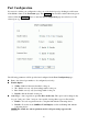
2.8.3 Ingress Rate Limit Config for Buckets To limit the traffic rate for specified port(s), click the Ingress Rate Limit Config for Bucket0 or Ingress Rate Limit Config for Bucket1 button in the Rate Control page to open the page for configuring the ingress rate limit for Bucket0 or Bucket1 respectively.
The maximum forwarding traffic rate will be limited by the percentage of rate for the current link speed on the specified ingress port. The following table shows the limited traffic speeds based on the different rates in different link speeds (10/100/1000Mbps). Rate Link Speed 100% 10Mbps 10Mbps 100Mbps 100Mbps 1000Mbps 1000Mbps 80% 8Mbps 80Mbps 800Mbps 64% 56% 6.4Mbps 5.6Mbps 64Mbps 56Mbps 640Mbps 560Mbps 48% 4.8Mbps 48Mbps 480Mbps 47% 32% 4.7Mbps 3.
2.9 Address Management The GSS-8T2SFP provides up to 10 static MAC address entries. These entries always exist in the switch’s address table and will never be dropped through normal switch MAC aging out. (All dynamic MAC entries from the address learning mechanism will be retained in the address table for up to 300 seconds.) If the switch administrator adds a static MAC address entry in to the switch and a 802.
Get/Refresh the Latest Address Management Settings Click the Address Management menu on the web page, the latest Address Management settings on the switch will be displayed. The following options are provided: n Add : Add a new entry into the static MAC entry table. n Delete: Remove an existing entry from the static MAC entry table. n Edit: Modify an existing entry in static MAC entry table.
2.9.1 Ø Ø Ø Ø Ø Add a New Entry Step 1: Click the Add button. Step 2: Choose the Port No. (e.g. : Port 3) Step 3: Enter the MAC Address. (e.g.: 31-32-33-34-34-36) Step 4: Enter the VLAN ID. (e.g. : 3333) (Range: 1 ~ 4094) Step 5: Choose the Priority. (e.g. : Priority = 3) After clicking the Apply button, the result will be shown on the page as below.
2.9.2 Ø Ø Ø Ø Ø Ø Modify an Existing Entry Step 1: Choose Entry No 1 and click the Edit button in the Static MAC Entry Table page. Step 2: Modify Port No to be Port 6. Step 3: Modify MAC Address to be 61-62-63-64-65-66. Step 4: Modify VLAN ID to be 666. Step 5: Modify Priority to be 6. Step 6: Click the Apply button. After clicking the Apply button, the result will be shown as below.
2.9.3 Delete an Existing Entry Choose a desired entry to be removed (e.g. entry1) and click the Delete button to complete the deletion. After deletion, the content in the Static MAC Entry Table will be refreshed.
2.10 System Configuration The System Configuration page provides the management information for the switch. The page shown below can be activated by clicking the Setup menu under the System section. The following parameters can be configured / displayed: n IP Address – the IP address used to manage this switch through the configuration port.
2.11 Account Settings Account setting is used to maintain the username and password for login validation. The switch provides only one login account for configuration management. Click the Account menu to activate the Account Setting page shown below: n n User Name – Set the username string (max. 6 characters) Password – Set the password string (max.
2.12 Reset System This switch can be rebooted or reset to default configuration. To reset the system, go to the Reset menu and open the following configuration page: This page provides two options : Ø Reboot Only – Reboot the system. All configuration settings will be retained to the latest changes before the reboot procedure. If you want to keep your configuration, select this option.
2.13 Firmware Update This switch provides the capability to update the firmware for new features, customized requests and system fault recovery. Click the Firmware Update menu to activate this page shown as below: Before you update the firmware, it is required to correctly prepare the BOOTP server (e.g. haneWIN DHCP server) and have the firmware file which will be uploaded to the switch by the BOOTP server available. (Please refer to the instruction guide for setting up the BOOTP server.
3 Application Notes 3.1 In-Band/Out-of-Band Switch Management n Out-of-Band Management To configure the switch, a network management station (NMS) normally can connect directly via the the Cfg Port. This kind of connection can be regarded as an out-of-band switch management as the configuration traffic is totally separate from the normal (in-band) traffic through the switch ports. An example figure for out-of-band management is shown as below.
n In-Band Management It is possible to achieve in-band management for the switch if necessary. The switch administrator needs to connect the Cfg Port to any of the normal switch ports (e.g. Port 1), then the NMS can be located anywhere within the network. The following figure shows a connection example for in-band switch management. IP 8G Smart Switch 192.168.1.254 C 1 2 3 Config Traffic 4 5 6 7 8 Switch Traffic NMS 192.168.1.100 PC2 192.168.1.