User Manual GSS-8T2SFPV2 8 Port Gigabit Web Managed Switch 8x 10/100/1000Mbps ports + 2 paired SFP Ports Version: 1.
Table of Contents CAUTION ---------------------------------------------------------------------------------------------------------- III ELECTRONIC EMISSION NOTICES ----------------------------------------------------------------------------- III AUSTRALIAN C-TICK COMPLIANCE --------------------------------------------------------------------------- III ABOUT THIS USER MANAUAL --------------------------------------------------------------------------------- 1 1.
3.4.1.7. Maximum Packet Length ---------------------------------------------------------------- 52 3.4.2. Warm Restart------------------------------------------------------------------------------------- 52 3.4.3. Restore Default Configuration---------------------------------------------------------------- 53 3.4.4. Logout---------------------------------------------------------------------------------------------- 53 4.
Caution Electronic Circuit devices are sensitive to static electricity. Dry weather conditions or walking across a carpeted floor may cause you to acquire a static electrical charge. To protect your switch, always: • Touch the metal chassis of your computer to ground the static electrical charge before you handle the switch. • Pick up the switch by holding it on the left and right edges only.
About this User Manual This User Manual will guide you on procedures to install, configure and monitor the GSS8T2SFPV2 8 port Gigabit Web Managed Switch utilizing the built-in web management interface.
1. Introduction 1.1. Overview of the 8 Port Gigabit Web Managed Switch The Alloy 8 Port Gigabit Switch meets all IEEE 802.3/u/x/z Gigabit and Fast Ethernet specifications. The 8 Port Gigabit Switch features 8x 10/100/1000Mbps copper RJ-45 ports and 2x paired Gigabit Ethernet SFP Ports.
• Key Features of the 8 Port Gigabit Web Managed Switch QoS: The GSS-8T2SFPV2 offers powerful Quality of Service (QoS) functions. This feature adds support of TOS fields within the IP packet header (equal DSCP low 3 bits) on Layer 3 of the network framework and 4 types of network transmission events on Layer 4. QoS support is important for real-time applications based on information taken from Layer 2 to Layer 4, such as VoIP. VLAN: The GSS-8T2SFPV2 supports both Port-based VLAN and IEEE802.
1.3. Features The Alloy 8 Port Gigabit Switch provides a comprehensive range of features: • Hardware • 8x 10/100/1000Mbps Nway Gigabit Ethernet copper RJ-45 ports • 2x SFP ports for optional Mini-GBIC fibre optic modules (paired with an RJ-45 port) • 144KB on-chip frame buffer • Jumbo frame support • Programmable classifier for QoS (Layer 4/Multimedia) • 8K MAC address and 4K VLAN support (IEEE802.1Q) • Per-port shaping, policing, and Broadcast Storm Control • IEEE802.
1.4. Overview of 8 Port Gigabit Switch Fig. 1.1: Front View of the GSS-8T2SFPV2 Switch 1.4.1. User Interfaces on the Front Panel (Button, LEDs and Plugs) There are 16x (GSS-16T2SFP model) or 24x (GSS-24T2SFPV2 model) copper RJ-45 Gigabit Ethernet ports and 2x SFP fibre ports for optional mini-GBIC modules (both models) on the front panel of the switch.
LEDS for: SFP Gigabit Fibre Ports 7 & 8 SFP(LINK/ACT) Green On when connection with the remote device is good Blinks when any traffic is present Off when module connection is not good Note: All SFP ports are paired with one of the 10/100/1000Mbps copper RJ-45 ports. Only one of the paired ports can be used. 1.4.2. User Interfaces on the Rear Panel AC Line 100-240V 50/60 Hz Fig. 1.
1.5. Overview of the Optional SFP Modules With the GSS-8T2SFPV2 switch, the SFP ports are paired with RJ-45 copper ports 7 and 8. Only one of any given paired port can be used. In this manner, these paired ports can be seen as ‘Dual Media’ ports that support 10/100/1000Mbps or 1000Mbps fibre via the SFP interfaces. Optional 1000Mbps mini-GBIC fibre transceiver modules can be used for high-speed uplink connections to fibre backbones or servers, when installed in the SFP ports.
2. Installation 2.1. Starting the 8 Port Gigabit Web Managed Switch This section provides a quick start guide for: • Hardware and Cable Installation • Management Station Installation • Software booting and configuration 2.1.1.
• Copper Ports - Cable Installation Please Note: ⇒ The RJ-45 ports on the Alloy 8 Port Gigabit Switch support MDI/MDI-X auto-crossover functionality. This enables use of either straight-through or crossover UTP cable types; the RJ-45 ports will automatically be configured to suit the characteristics of the device at the remote end of the link.
2.1.2. Cabling Requirements To help ensure a successful installation and keep network performance at optimum levels, take care to use Cat.5E grade or higher cabling. Ensure that stranded core UTP cable, if used, runs for no more than 10 metres, and that solid core runs for a maximum of 100 metres. Poor cabling is the most common cause for network dropouts or poor performance. 2.1.2.1. Cabling Requirements for UTP Ports • For Ethernet copper network connections, the UTP cable used must be Cat.
Please Note: ⇒ Further information can be found in section 1.5 on page 7 ⇒ All figures denoting the range a given cable type can achieve must be treated as maximum values.
3. Operation of Web-based Management This chapter instructs you how to configure and manage the Alloy 8 Port Gigabit Web Managed Switch through the web user interface. The default values of the GSS-8T2SFPV2 Gigabit Web Managed Switch are as follows: IP Address 192.168.1.1 Subnet Mask 255.255.255.0 Default Gateway 192.168.1.254 Default Password admin Browse the switch via its IP address http://192.168.1.1.
3.1. Web Management Home Page Overview After you have successfully logged into the management interface screen, the system status information is displayed as in Fig. 3.2. This page informs you about the basic information of the system, including “Switch Status”, “TP Port Status”, “Fibre Port Status”, “Aggregation”, “VLAN”, “Mirror”, “Trap Event”, and “Maximum Packet Length”. From this information, you can ascertain the software version used, MAC address, port status and so on.
The functions of each group are described in the corresponded sections through the remainder of this manual. The organization of the submenus shown in diagrammatical format is shown in Fig. 3.3 Main Menu Configuration Monitoring Fig. 3.3 Maintenance 3.2. “System” – The System Configuration Submenu 11 functions are included in the System Configuration group. Each of them will be described in detail in the following sections. In diagrammatical format, the functions are (Fig. 3.
3.2.1. System Configuration System configuration is one of the most important options in the management of the switch. Without proper configuration, the switch cannot be accessed or managed. The switch supports manual IP address settings. When the IP address is changed you must reboot the switch to have the settings take effect. Changing the IP address will require you to change you management IP in your web browser. Fig. 3.
Cont. Subnet Mask (RW): * Use to configure the Subnet Mask setting, then click button to update. Default value: 255.255.255.0 Default Gateway (RW): * The Default Gateway is used in routed networks to determine the net hop for all non local destinations. Click the button to update the field. The default value is: 192.168.1.254 System Name (RW): * Used to set a logical name for the switch. Up to 16 alphanumeric characters and nulls are allowed in this parameter.
3.2.2. Port Configuration Submenu • Function Name: Port Configuration Fig. 3.6 • Function • Description: Port Configuration allows the various port settings to be changed • Parameter Description: Mode: * Used to set the speed and duplex parameters of a port. * If the media is 1Gbps fibre, then there are three modes to choose from: ‘Auto Speed’, ‘1000 Full’ and ‘Disable’. * If the media is UTP (copper), then there are additional Speed/Duplex settings. Speed modes are: ‘10’,’100’ or ‘1000Mbps’.
3.2.3. VLAN Mode Configuration Fig. 3.7 The switch supports Port-based VLAN and Tag-based VLAN (802.1q). 8 active VLAN’s are supported, with VLAN ID’s from 1-4094. VLAN configuration is used to partition your LAN into small broadcast domains (groups). Properly configuring VLANS can improve your network security and increase network performance by limiting broadcast propagation.
port-based VLAN, in that tagged VLANs can exist as groups across multiple switches in your enterprise whereas port VLANS are local only to the switch that they are defined on. Port ingress (incoming) and egress (outgoing) rules allow for filtering of packets that don’t conform to your specific policies on accepting or denying nontagged packets. Each tag-based VLAN that is configured must be assigned a VLAN name and a VLAN ID. Valid VLAN ID’s range from 1 to 4094.
Fig.3.7a • Function Name: Management Interface • Function Description: • Parameter Description: There two options available Enabled or Disabled. This allows you to change what VLAN ID the management interface is able to be configured on. This is only available when using Tag-Based VLAN’s. State: *Disabled: *Enabled: *VID: Disable Management VLAN ID, management interface is accessed only by ports with VLAN ID 1.
Fig.3.
3.2.4. VLAN Group Configuration 3.2.4.1 Port-based VLAN Configuration Fig. 3.8 • Function Name: Port-based VLAN Configuration • Function Description: • Parameter Description: Here you can configure port-based VLAN’s, this will display the ID, Description and associated members. You can easily create and delete VLAN groups by using the and function buttons, or click the Group ID directly to edit it.
Fig. 3.8a Delete Group: * Select the check box (;) beside the ID, to delete a group. Then press the button to delete the group. Fig. 3.
3.2.4.2 Tag-Based VLAN Configuration Fig. 3.8c • Function Name: Tag-based VLAN Group Configuration • Function Description: • Parameter Description: Here you can configure Tag-based VLAN’s, this will display the ID, Description, VID and Members of the existing tag-based VLAN group.
Fig. 3.8d Delete Group: * Select the check box (;) beside the ID, to delete a group. Then press the button to delete the group. Fig. 3.
3.2.4.3 Metro Mode VLAN Configuration Fig. 3.8f • Function Name: Metro Mode VLAN Configuration • Function Description: • Parameter Description: Here you can configure Metro Mode (port-based) VLAN’s, this will display the ID, Description and associated members. You can easily create and delete VLAN groups by using the and function buttons, or click the Group ID directly to edit it. ID (Group ID): * This is the Port Based VLAN ID for the VLAN that you are creating.
3.2.5. PVID Configuration Fig. 3.9 • Function Name: PVID Configuration • Function Description: • Parameter Description: From within this menu users can assign a VID number for each port. The range of VID numbers is from 1 to 4094. You can also choose ingress filtering rules to each port. There are two ingress filtering rules which can be applied to the switch. Ingress Filtering Rule 1 is “forward only packets with VID matching this port’s configured VID”.
VLAN100. If it is, then the received packet is forwarded; otherwise, the received packet is dropped. Rule 2: * Drop untagged frame. You can configure a given port to accept all frames (Tagged and Untagged) or just receive tagged only frames. If the former is the case, then packets either tagged or untagged will be processed. If the later is the case, only packets carrying a VLAN tag will be processed, all other packets will be discarded.
3.2.6. Aggregation Configuration Aggregation (Port Trunking) Configuration is used to configure Link Aggregation. You can bundle more than one port with the same speed and duplex settings to form a single logical port. The logical port aggregates the bandwidth of the individual member ports. This allows you to create a higher speed uplink or backbone connection via bandwidth aggregation.
3.2.7 Mirror Configuration Fig. 3.11 • Function Name: Mirror Setting • Function Mirror Configuration is used to monitor the traffic on Description: the network. For example, assume that Port A is a ‘sniffer’ port and Port B is the Source Port; configuring a mirror setting allows the traffic passed by Port B to be copied to Port A for monitoring purposes • Parameter Description: Sniffer Mode: * Used for the activation or de-activation of the Port Mirror function.
3.2.8. Quality of Service (QoS) Configuration The switch offers powerful QoS functions including: VLAN tagged priority for 8 levels, TOS field IP header (equal DSCP low 3 bits) on Layer 3 network framework, 7 types of layer 4 network transmission events, and IP DiffServe QoS services. In the Quality of Service (QoS) Configuration management interface there is an option named ”Default Class”.
Fig. 3.12a • Function Name: VLAN Tag Priority • Function VLAN tags have 3 bits that belong to a priority flag. Description: These 3 bits can define 8 traffic classifications. The classifications can then be mapped to ‘High priority’ or ‘Low ‘ priority queues.
Fig. 3.12b • Function Name: Quality of Service (QoS) ToS Configuration: • Function Description: Within the Layer 3 network framework is a TOS field for IP headers. The Alloy 8 Port Gigabit Switch can prioritise packet forwarding based on this TOS header. TOS Headers include 3 bits for 8 levels of TOS. Once again these 8 levels can be mapped to ‘High’ or ‘Low’ priority queues.
Fig. 3.12c • Function Name: Quality of Service (QoS) Layer-4 Configuration: (Mode Selection Screen) • Function Description: In Layer 4 QoS Configuration you can prioritise packets based on the application type that they contain; for example, to down prioritise web browsing, e-mail and FTP. • Advanced/: Simple Mode Toggle the / button to switch between configuration modes and to display details on the TCP/UDP ports configured (See Fig 3.12d).
Fig. 3.12d • Advanced: Mode The Advanced Configuration Mode interface box allows you to further customise the initial simple configuration defaults with your own TCP/UDP port definitions, or to create your own definition list from scratch. (Refer to Fig 3.
Fig. 3.12e • Function Name: IP DiffServe Classification • Function IP DiffServe Classification supports up to 64 (0-63) Description: Traffic Classifications based on a 6-bit field in the DSCP header of IP packets.
3.2.9. Bandwidth Management Fig. 3.13 • Function Name: Bandwidth Management Configuration • Function The Bandwidth Management function is used to set Ingress Description: and Egress bandwidth limits for each port • Parameter Description: Port Number: * Select the port to which you want to add a Rate Control Policy. Optionally, you can select to control all ports at the same time from the “All” selection All Traffic for Ingress Rate Limiting: * Define the rate for incoming traffic on the selected port.
3.2.10. Trap Event Configuration Fig. 3.14 • Function Name: Trap Event Configuration • Function Description: The Trap Event Configuration interface screen enables the Alloy 8 Port Gigabit Switch to send out trap information when predefined events occur on the network. The switch offers 7 different trap events and 2 configurable destination Trap Hosts. Trap messages are enabled by selecting the tick (;) box beside each event description.
3.2.11. Maximum Packet Length Fig. 3.15 • Function Name: Maximum Packet Length • Function Description: The switch is capable of dealing with 9k Jumbo Frames. Jumbo frames are effective in point to point environments for large payload data transfers. They maximise the data-toheader payload ratio, so that more data is sent with less header information (note that both transmitting and receiving nodes need to support Jumbo Frames) • Parameter Description: Max.
3.3. Monitoring There are two functions contained in the monitoring section of the management. Monitoring Statistics Overview Detailed Statistics 3.3.1. Statistics Overview The Statistics Overview function collects summary information from port-based traffic counters. The type of data that can be collected includes information about Frames, Bytes, and Errors. In Fig. 3.16, all ports are displayed in a summary format. If any counter overflows its maximum level, then it will reset and resume from 0 (zero).
3.3.2. Detailed Statistics Fig. 3.17 • Function Name: Detailed Statistics • Function Displays detailed counter information for a specific port Description: (See Fig. 3.
Tx Multicast: * Number of multicast packets transmitted Rx 64 Bytes: * Number of 64-byte frames (includes non valid packets) received Fig. 3.
Tx 256-511 Bytes: * Number of 256 to 511-byte frames (includes non valid packets) transmitted Fig. 3.
prescribed standards), or frame aging. Tx FIFO Drops: * Total frames dropped due to the Transmit Buffer being full Fig. 3.
3.4. Maintenance There are four functions contained in the maintenance section. Maintenance Status Warm Restart Factory Default Logout 3.4.1. Status 8 sections are reported on in the switch status screen.
3.4.1.1. Switch Status • Function Name: Switch Status • Function Display the status information of the switch Description: Fig. 3.21 • Parameter Description: Product Name: * Provides a description of the specific switch model (i.e.
3.4.1.2. UTP & Fibre Port Status Fig. 3.22 • Function Name: TP/Fibre Port Status • Function Displays a summary of the port status for both TP and Fibre Description: ports • Parameter Description: Port: * Ports 1 to 8.
Flow Control: * Displays flow control status active for individual ports. Two options are available to choose from: and . The default mode is . There are two types of Flow Control supported by Ethernet (Both supported by Alloy Gigabit Switches): o Pause flow control: As stipulated by IEEE standard 802.3x, for fullduplex operation o Backpressure: For half-duplex operation 3.4.1.3. Aggregation Fig. 3.
3.4.1.4. VLAN • Function Name: VLAN Status • Function Description: Display which VLAN mode the switch is operating with, and details of VLAN group settings. • Parameter Description: VLAN Mode: * Displays the 3 supported VLAN modes, with status displayed for each mode.
3.4.1.5. Mirror Fig. 3.27 • Function Name: Mirror Status • Function Description: • Parameter Description: Mirror Status displays the current mirror configuration Sniffer Mode: * Displays the mirror status. The default is “disabled” Sniffer Port: * Displays the number of the port that is receiving the monitored data Source Port: * Displays the number of the port that is being monitored 3.4.1.6. Trap Event Fig. 3.
• Parameter Description: Trap IP (1 and 2): * The IP address of 1 or 2 two P.C.’s which can access trap event data and receive trap event warnings can be entered here. Current IP addresses are displayed as status information Boot: * Two parameters are available for Boot Traps. The associated tick boxes are endorsed to activate trap data/warnings. The parameters are: o Warm Boot o Cold Boot Login: * One parameter is available for Login Traps – “Illegal Login”.
3.4.1.7. Maximum Packet Length Fig. 3.29 • Function Name: Maximum Packet Length • Function Description: Display’s the maximum packet length setting on a per port basis • Parameter Description: Max. Frame Size: * Displays the current setting of the maximum packet length on a per port basis. Values displayed are from a range of 1518 bytes, 1532 bytes or 9208 bytes 3.4.2. Warm Restart The management interface for the Alloy 8 Port Gigabit Switch offers a Warm Restart option.
3.4.3. Restore Default Configuration Fig. 3.31 • Function Name: Restore Default Configuration • Function Description: The Factory Default function will reset the current configuration settings of the switch, and replace them with the original Factory Default settings. 3.4.4. Logout Alloy 16/24 Gigabit Switches supports a web management auto-logout (see section 3.2.1) from the web interface, but there is also a manual logout function.
4. Maintenance and Basic Troubleshooting New generation switches are in most respects a ‘black box’ solution in terms of the basic installation and connection of network nodes (workstations, servers, subsidiary switches etc). Many discrete components that were present in earlier generation switches have now been ‘folded’ into the ASIC chipset of modern switches. Factors such as these have greatly enhanced the ease of use, reliability and maintenance of these devices.
should be checked in the advent of certain types of difficulties with the basic operation of the switch: • The Switch Fails To Power up: ⇒ Ensure the AC power cord is connected to the mains outlet and the switch AC power inlet correctly, and both the mains socket and the switch is turned on otherwise ⇒ Check and ensure that the mains circuit from which the switch is drawing power is functioning • One or More Ports Fail to Link: ⇒ Ensure the switch is powered on (see above) ⇒ If you have just powered
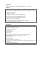
Appendix A Technical Specifications Key Features • 8x (10/100/1000Mbps) Gigabit Ethernet (TP) switching ports compliant with IEEE802.3, 802.3u, 802.3z and 802.3ab • 2 Gigabit Copper/SFP paired ports for support of Fibre or Copper Mini-GBIC media. SFP ports are paired with TP ports 7 and 8.
Hardware Specifications Standards Compliance: IEEE802.3/802.3ab / 802.3z / 802.3u / 802.3x Network Interface: Configuration Mode Connector 10/100/1000Mbps Gigabit copper Nway TP (RJ-45) 1000Base-SX Gigabit Fibre 1000 FDX SFP 1000Base-LX Gigabit Fibre 1000 FDX SFP 1000Base-LX Single Fibre WDM 1000 FDX SFP 1 Port 1–8 2 7, 8 2 7, 8 2 7, 8 Notes: 1: Ports 7 & 8 are paired copper TP RJ-45/SFP fibre module slot dual media ports.
Maximum Cable Length: TP Cat. 5 UTP cable or higher, max.