
User manual


POEFE24TV2 User Manual
Alloy Computer Products Pty Ltd Copyright ©2012
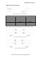
Appendix A. RJ-45 Connections
RJ-45 Connector pin out
Pin no.
MDI-I signal
MDI-X signal
1
TX+
RX+
2
TX-
RX-
3
RX+
TX+
4
not used
not used
5
not used
not used
6
RX-
TX-
7
not used
not used
8
not used
not used
Below is a diagram of a typical straight through and cross-over cable connection:
Fig. 4 RJ-45 Connectors, switch and cable views
Fig. 5 Straight Through Cable connection
Fig. 6 Cross-Over Cable connection