
Use and Care Manual


6
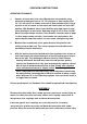
ASSEMBING THE ABRASIVE BLASTER
1. Refer to the drawing for step 1, assembling the intake manifold (15).
First, attach the pressure gauge (16), to the top of the intake
manifold, turning the gauge so that is can be see across the top of
the tank. Next, attach the throttling valve (19A) to the bottom of the
manifold. Attach the nipple connector (21), to the throttling valve.
Attach the joint pipe (14), to the manifold.
2. Refer to the drawing for step 2, to assemble the water trap filter (18).
nipple connector (17) is screwed into each side of the filter. On
one side, attach the air supply valve (19), to the nipple connector (17),
and then attach the male/female connector (20), to the other
side of the air supply valve. When you’re ready to operate the
abrasive blaster, the air hose from the compressor will fasten to the
male/female connector (20).
3. Place the tank (01) on a table with the four clips up. Refer to the
drawing for step 3. Screw the water trap filter (18) and its parts into
the hole at the side of the intake manifold. Then screw the open end
of the joint pipe (14) with intake manifold (15) and pressure gauge
(16) attached into the threaded hole on the side of the filler pipe on
Top of the tank. Again, be sure that the manifold and gauge are vertical.
4. Refer to the drawing for step 4, assembly of the abrasive outlet valve
into the hole at the bottom of the tank; Attach four parts, in order:
Nipple connector (17); abrasive metering valve (19B); nipple
Connector (17) and the abrasive outlet pipe (23).
5. Refer to the drawing for step 5, assembly of the nozzle DEADMAN
valve(34). In this assembly process, you’ll select one of the four
nozzles (28). This is not a permanent selection, as you may change
nozzles according to the job being done. Screw the adapter (26), into
the nozzle DEADMAN valve (34). Screw the gasket (27) into the nipple
connector, then add a nozzle (28) and the nozzle cap-nut (29).
6. Refer to the drawing for step 6, for connecting the abrasive metering
valve assembly (step 4) and the assembly (step 5).
Slide the two hose clamps (24), over each end of the abrasive hose (25),
press one end of the hose, over the nipple on the abrasive outlet
pipe (23) and the other end over the adapter (26). Both hose
ends should be firmly seated on the nipples. Slide the hose clamps
along the hose to each nipple and tighten the clamps very firmly.
7. Fasten the two handlebars (06) to the tank using four pan screws (08)
and four washers (10) and four hex nuts (09). Note: keep the handle
curve ends upward.
8. Locate the axle (05), and slide it through the holes in the sides of the
handlebars (06). Place one wheel (02) at each end of the axle and
fasten then into place with cotter pins (03) and washer (30).
9. Insert the fixed foot (04) onto the fitting on the bottom of the tank
near the edge. Use your last cotter pin (03) to hold the foot to the
tank.
10. Before beginning operations, go back over each connection, double
checking to ensure that all are tight and properly seated.