COPYRIGHT The entire contents of this manual, including any future updates, revisions, and modifications to specifications, shall remain the property of Alltek Marine Electronics Corp. (hereinafter AMEC) at all times. Unauthorized copies or reproductions of this manual, either in part or as a whole, are strictly prohibited. The contents herein can only be used for the purpose subjects to this manual. DISCLAIMER AMEC is devoted in publishing and maintaining this manual.
WARNING! Please carefully read this manual before start using the AIS AtoN device. This product is an auxiliary monitoring device, and it should not be relied upon as the sole monitoring navigation system. Failure to operate this system in accordance with the operating instructions specified in this manual may result in unreliable or reduced system performance. Improper operation or installation may cause damage to the equipment or injury to personnel.
Table of Contents I. II. III. COPY RIGHT & DISCLAIMER WARNING & SAFETY INSTRUCTION FORWARD Pages 1 INTRODUCTION ................................................................................................ 1 1.1 MANDO-301/303 Overview .................................................................................................. 1 1.2 MANDO-301/303 Features ................................................................................................... 4 1.3 Type of AIS ..........................
4.5.6 All Settings Complete ................................................................................................. 36 4.6 Message Scheduling ......................................................................................................... 36 4.7 Chaining Configuration..................................................................................................... 43 4.8 Delete Selected Child/Parent MMSI..................................................................................
1 INTRODUCTION 1.1 MANDO-301/303 Overview Aids to Navigation (AtoN) AIS is one of the latest applications of AIS technology. The AIS AtoN transponder can be installed in lighthouse, lantern, buoy, other fixed and floating aids, or offshore platforms to transmit warning, navigational, and meteorological data to approaching vessels and/or to shore stations. AMEC offers two types of AIS AtoN: MANDO-301 (Type 1) and MANDO-303 (Type 3).
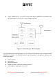
Type 3 (MANDO-303) – It has AIS receive and transmit capabilities in accordance with Recommendation ITU-R M.1371. Using FATDMA/RATDMA. GPS Antenna VHF Antenna Figure 1-1-2 AIS AtoN Type 3 Block Diagram A pre-programmed transmitting schedule can be configured to broadcast AtoN messages through FATDMA or RATDMA.
In normal conditions, the unit transmits a report with AIS AtoN position in an ITU-R M.1371 message 21. In addition, the AIS AtoN broadcasts AIS Message 6, which enables the operator to monitor the AtoN device for solar/battery voltage, flash setting and light status. Subject to the fitting of appropriate measuring devices, meteorological/hydrological data and other parameters can be obtained via Message 8. A brief summary of all the messages processed by the AIS AtoN are defined in section 1.4.
1.2 MANDO-301/303 Features Low power consumption Operation condition: 12V DC, reporting interval 3 minutes. - MANDO-301: FATDMA: < 0.288 Ah/day MANDO-303: FATDMA: < 0.432 Ah/day RATDMA: < 1.
1.3 Type of AIS The marine Automatic Identification System (AIS) is a location and vessel information reporting system. Some elements of AIS networks are illustrated in the following table: Table 1-3 Type of AIS elements Class A AIS Transponder ‧ Transmits and receives AIS signal. ‧ Intended for vessels meeting the requirements of IMO AIS carriage requirement. ‧ It is mandatory for all commercial vessels that exceed 300 tons to be equipped with Class A AIS.
1.4 AIS AtoN Message Table 1-4 Summary of AIS AtoN Messages supported by Mando Series Message ID Message Type Slot Length Description Binary payload that contains the MMSI, usually of a base Addressed 6 Binary Message station, which is designated to receive the message that is 1 to 5 (varies) sent until it is acknowledged; May contain information about the AtoN equipment, such as meteorological and hydrological information that is obtained from a daughterboard or external sensors.
1.5 About This Manual The manual contains installation instructions and operating information for MANDO-301/303. While most of the installation can be performed by the user, a final commissioning can be done by your local agent/dealer where needed or required. AMEC and the local agent/dealer will not bear any responsibilities over any damages resulted in improper installation by unauthorized agent/dealer.
2 INSTALLATION 2.1 General 2.1.1 Safety Instructions Before proceeding with installation, please take note of the following safety instructions and read through this installation manual carefully. SAFETY INSTRUCTIONS SAFETY INSTRUCTION PLEASE FOLLOW THIS INSTRUCTION MANUL TO PROCEED WITH THE INSTALLATION. AMEC and your local agent/dealer will not bare any responsibility of equipment damage or personnel injury due to improper installation.
2.1.2 Items in the Package Table 2-1-2 Items in the Package No. 1 2 3 Description MANDO-301/303 AIS AtoN main unit Installation Kit Qty 1 Power cable 1.5M, AWG 16 1 8 pin connector with waterproof cup, cable 1M, AWG 24 1 12 pin connector with waterproof cup, cable 1M, AWG 26 1 M4×6 Screw 8 1/4×3/4 Screw 4 CD-ROM: AMEC AtoN Configuration and Operation Manual 1 2.
Installation: Horizon Type A. Fix the mounting plat B. Use the self drilling screw C.
Installation: Vertical Type D. Fix the mounting plat E. Use the self drilling screw F.
2.3. MANDO-301/303 External Connections GPS Antenna VHF Antenna Hydrological / Weather R Battery / Solar Power PC / NB *NOTE: CON1 and CON2 can be alternately used.
2.4. Installing VHF Antenna Installation of a VHF antenna is as important as the transceiver for reliable communications. Please check the following picture and caution for your installation references. POWER Connector M Jack/PL-259 VHF 5D-FB cable Figure2-3 Installing VHF Antenna When installing VHF antenna, please follow all of the manufacturer's instructions with particular attention to the cable routing and connection. (For better product performance, AMEC VHF antenna is highly recommended.
Avoid the antenna be surrounded by any obstacle or metal object due to signal interference. Do not stabilize the VHF antenna with metal holder. The bottom of the VHF antenna is the signal receiving blind spot. Keep the antenna cable as short as possible. The antenna cable diameter should be 5D/8D or even better ones. Avoid bare wire winding & insulating tape wrapping when connecting with extended antenna cable.
2.5. Installing GPS Antenna Since the punctuality of internal transmission of the AtoN device relies on the accuracy of the time signal obtained from the GPS system, the correct installation of GPS antenna is essential. When installing GPS antenna, please follow all of the manufacturer's instructions with particular attention to the cable routing and connection. (For better product performance, AMEC GPS antenna is highly recommended.
When installing the GPS antenna, follow the cautions below. Ensure the cable connector is carefully secured. Position the antenna as high as possible to prevent ice or spray from negatively affecting signal reception. Be sure no obstructions are between the GPS antenna and the sky. Place the GPS antenna at least 3m from the VHF antenna due to signal interference. Installation Process 1) Place the GPS antenna mounting bracket on a rigid surface and install the antenna.
3 WIRING DIAGRAM/PIN DEFINITION Power Connector 1 2 3 Figure 3-1 Pin Assignments Front View Pin number Pin definition Description Positive (+), Color 1 PWR 2 N/A N/A N/A 3 GND Power ground Black the input should be 12V DC 17 Red
Con1: (ADC & RS-232 ) Figure 3-1 Pin Assignments Front View (Part No.
Con2: (Control, Monitor & RS-232) Figure 3-2 Pin Assignments Front View (Part No.: LTWBD-08BFFM-LL7A01 by Amphenol LTW) Pin number Pin definition Description Color 1 RS232_RX Configuration interface Black 2 RS232_TX Configuration interface Brown 3 GND Signal ground (RS-232) White 4 ALM_C ALARM C Blue 5 ALM_B ALARM B Red 6 ALM_A ALARM A Orange 7 CTL_IF Digital in signal Yellow 8 V_CTL Digital in power Green *NOTE : 1.
4 MANDO-301/303 CONFIGURATION 4.1 Configuration Start-up Step 1: Connect the AtoN device with PC/Laptop via RS-232 serial port. Prepare a RS-232/USB converter when RS-232 serial port is not supported by your PC/Laptop. Step 2: Connect the AtoN device with 12V DC (10A) power source. It is highly recommended to use a power adapter stabilizing the power source. Step 3: Power on the AtoN device. Step 4:Turn on PC and load AMEC Configuration Program CD.
4.2 Serial Port Searching Windows VISTA version Click on “Start” Select “My Computer” Mouse right click “Properties” Select “Device Manager” Click Port (COM&LPT) Windows XP version Click on “Start” Select “My Computer” Click “Control Panel” Select “System” Choose “Hardware” Select “Device Manager” Click Port (COM&LPT) Choose the Prolific RS-232-to-Serial Com Port (Com3) as designated port numbers. Figure 4-2 Serial Port Searching 4.2.
Step 1: Start AMEC MANDO-301/303 Configuration Program. Step 2: Enter the corresponding Serial Port & Baud Rate information. Step 3: Click “Connect” to complete and save the setting. Figure 4-2-1-1 Serial Port Setting *NOTE: Only “Serial Port” and “Baud Rate” need to be set, other parameters are default. AMEC MANDO-301/303 default Baud Rate is 115,200-bps.
remind you to re-check Serial Port.
If you do not connect Power or other problem, PC/Laptop will jump up a window to remind you to re-check all connection.
4.2.2 VDL Setting If your device is MANDO-303 (Type 3), you could remote other MANDO-303(Type 3) via VDL. Step 1: After setting Serial Port and connecting with PC/Laptop, please choose “VDL”. Step 2: Enter desired MMSI which you would like to remote control. Step 3: Click “Connect” to complete and save the setting. Figure 4-2-2 VDL Setting *NOTE: After setting the “VDL”, you can continue setting the following tabs.
4.3 AtoN MMSI Setup Step 1: Enter the valid MMSI number under “MMSI” column. Step 2: Select “Real AtoN” under the “Real / Virtual” column. Step 3: Click “Create” to save and create the new MMSI. Step 4: Press “Read Device” to confirm and review the MMSI setting. Figure 4-3-1 AtoN MMSI Setup *NOTE 1: The MMSI number is controlled by a competent authority and must be a legitimate number. *NOTE 2: The default MMSI number is 000000000.
Please follow all steps above to create Virtual MMSI or Synthetic MMSI. Check if there are all correct MMSI data saved in the “MMSI” column.
4.4 Delete Selected MMSI Select the desired MMSI to be deleted under the “MMSI” column. Right-click and it will jump up window written “Delete”. Click “Delete” to erase all setting of this MMSI number.
4.5 AtoN Station Data Setting Step 1: After the MMSI (Real/Virtual/Synthetic) is successfully setup, user can continue with rest of AtoN station data setting. Step 2: After all AtoN device data setting, please click “Config Device” button to save the data when all settings are completed. PC/Laptop will pop-up window said “Configuration done!”. Then press “OK” to complete the setting. Step 3: Click “Read Device” to check and make sure all AtoN settings are correct.
4.5.1 Name and Type of AtoN Device Step 1: Enter the name of AtoN device. Step 2: Select the correct type for the AtoN device.
4.5.2 Position Information Step 1: Select the type of EPFS and position accuracy information. Step 2: Enter the Latitude and Longitude of the AtoN position. Step 3: Choose 8-bit data for AtoN Status. (“V” means 1; Empty means 0.) 1. Bit 7, 6, 5 mean Page ID. For example: Page 7 (binary 111); 2. Bit 4, 3 mean RACON status; 3. Bit 2, 1 mean Light Status; 4. Bit 0 means status.
4.5.3 Transmit Setting Step 1: Choose the desired output power of 2W, 5W, or 12.5W. Figure 4-5-3-1 Transmit Setting *NOTE: The output power can only be setup at the Real AtoN. NOTE: If user makes configuration via the configuration port using the ACF sentence below: “ $--ACF,xxxxxxxxx,x,llll.llll,a,yyyyy.yyyy,a,x,xxxx,xxxx,xxxx,xxxx,x,xx,x,a*hh”, the manufacturer “Power level code” are defined as follows: Power level of ACF sentence (Note 5)* Tx power (Watt) 0 12.
Step 2: Adjust the frequency of Channel 1 and Channel 2. Figure 4-5-3-2 Transmit Setting *NOTE: The Channel Setting can only be setup at the Real AtoN.
4.5.4 Off Position Step 1: Enter the desired meter of Threshold. When the position of buoy exceeds the Threshold, MANDO will enter into the off position status. Step 2: Please select transmission schedule when it is off position. (If user choose “Use new reporting interval”, user has to set Msg 21“Off-Pos” on “Message Scheduling” tab.
4.5.5 Dimensions Enter the distance of relative position between the GPS antenna and buoy at the Dimension/ Ref. for position column, while the black spot in the picture represents the location of GPS antenna. (Unit: Meter) Figure 4-5-5 Dimensions *NOTE 1: The dimensions are NOT allowed to configure at Virtual/ Synthetic AtoN. *NOTE 2: The dimension diagram shows a vertical view which indicates the distance between the GPS antenna and periphery of the buoy.
4.5.6 All Settings Complete Step 1: Click on “Config Device” to finish and save all AtoN settings. Step 2: Select “Read Device” to review and confirm all settings.
4.6 Message Scheduling Step 1: Choose the desired MMSI number (Real/ Virtual/ Synthetic) to be scheduled under the “MMSI List” column for further message scheduling. Figure 4-6-1 Message Scheduling *NOTE: Please setup the MMSI number before starting message scheduling settings.
Step 2: For Real AtoN, select the Message ID to be scheduled from the following: Message 6, 6 (Lantern Monitor), 8, 8(Metro. & Hyd. monitor), 12, 14, 21(On-Pos), 21(Off-Pos) and Chaining. Please refer to Figure 4-6-2.
Step 3: For Virtual or Synthetic AtoN, one could select only Message 21(On-Pos) to be scheduled.
Step 4: Select the desired Access Scheme: FATDMA or RATDMA (For MANDO-303 only) Step 5: Click the checkbox of “Channel 1 Setting” and “Channel 2 Setting” to setup the broadcast timing and period parameters (User could choose Single Channel or Dual Channels). Step 6: Use the arrow keys to adjust each parameter to setup report rate. Figure 4-6-4 Message Scheduling *NOTE1: To stop broadcasting the message, please click on the “Disable” checkbox. *NOTE2: FATDMA could choose “Start Slot” parameters.
For UTC Hour, Minute, Start Slot and Interval, these are for starting (initial) UTC time for your message scheduling report. MANDO-301/303 will follow the UTC time from GPS and according to your message scheduling settings (UTC hour, UTC minute, Start Slot, Interval) to calculate the nearest next transmitting time. Example 1, FATDMA: UTC hour: 0 ; UTC minute : 1; Start Slot : 150 (4 seconds); Interval : 10 minutes. (If the UTC time from GPS is 18:03:00 – according to the Example 1.
Select “Config Device” to save and input the settings into the AtoN device. It will pop up a window said “Configure done!” Now press “OK” to complete it. Press “Read Device” to confirm and review the current device scheduling status. Figure 4-6-5 Message Scheduling *NOTE: On the MMSI List, if Msg is with If Msg is with , it means this message schedule is set already. , means this message schedule is not set yet.
4.7 Chaining Configuration Chaining Configure is for MANDO-303 (Type 3) only. If the device is not MANDO-303 (Type 3), the tab will be closed automatically. For MANDO-303, please follow steps as below: Step 1: Enter the desired MMSI number on “Chaining MMSI” column. Step 2: Select Parent MMSI or Child MMSI on “Parent/ Child” column. Step 3: Click on “Create MMSI” first to create and save this chaining. Step 4: Click on “Read Device” to ensure all settings are properly saved.
After setting Chaining, please choose “Message Scheduling” tab, and select Msg “Chaining” under Real AtoN Station to set up for further transmitting report rate. Figure 4-7-2 Chaining Configuration *NOTE: All steps are the same as setting “Message Scheduling” when you complete the “Chaining” Setting.
4.8 Delete Selected Child/Parent MMSI Step 1: Select the desired MMSI to be deleted under the “MMSI Chaining List” column. Step 2: Right-click and press “Delete” to erase all setting of this certain MMSI number.
4.9 Auxiliary There are three different parts in this column. User could set those items one by one. Standby Mode: Please choose desired wake up time on “Standby Mode”. Please use the arrow keys. Off-Pos MSG: Please write down the desired words/characters on each Message Test Content that is used for SRM Message while it is off position. (There are 50 characters limited) Repeat: User could choose the desired Message – Message 6, Message 8, SART – to repeat these three Messages for other AIS AtoN Device.
4.10 Version Please press “Read Device” to confirm and review the current device information, including Device Type, Vendor ID, Manufacturer Serial Number, Software and Hardware Version (Revision).
5 APPENDIX 5.1 Product Specifications APPLICABLE STANDARDS IEC 60945 Ed. 4 IEC 61162-1 Ed. 3 IEC 62320-2 Ed.1 IEC 61108-1 Ed. 2 (2002-05) (2007-04) (2008-03) (2003-07) IEC 61108-2 Ed. 1 ITU-R M.1371-4 IALA A-126 Ed 1.4 (1998-06) (2010-04) (2008-06) POWER SUPPLY Input Voltage 12V DC nominal (at Power Connector) POWER CONSUMPTION @ 12V DC MANDO-301 FATDMA< 0.288 Ah/day * MANDO-303 FATDMA< 0.432 Ah/day * RATDMA< 1.656 Ah/day * * At 12.
RECEIVER PERFORMANCE (Type 3 Only) Numbers of Receivers RX Frequency Range Sensitivity Data Rate PER Co-Channel Rejection Adjacent Channel Rejection Nominal Impedance 2 156.025MHz ~ 162.025 MHz PER 20% at -107 dBm 9,600 bps 20% at -107 dBm 10 dB at 1 KHz offset 70 dB at 25 KHz 50Ω GPS RECEIVER Receiving Channels Tracking &Navigation Sensitivity Reacquisition Sensitivity Horizontal Position 50 channels ≧ -159 dBm ≧ -159 dBm < 2.5 m Autonomous < 2.0 m SBAS Receiver Type SBAS: WAAS, EGNOS.
INPUT / OUTPUT 1) One RS-232 port for configuration 2) One RS-232 port for communication 3) One isolated control output – N.C. relay for alarm indication (default) or other control usages 4) One isolated status input channel with 5 mA constant current sink for external device status input (e.g. read light fault, light on/off, etc.
5.
Figure 5-2-2 Interfaces of AIS AtoN Figure 5-2-3 Side View of AIS AtoN 52
Figure 5-2-4 AIS AtoN Module Figure 5-2-5 AIS AtoN Module 53
5.3 Accessories The following accessories are available from AMEC. Contact our local dealer/agent for more details. Table 5-3 Accessories Item Description Product Code 1 VHF Antenna TENTA-11 2 GPS Antenna AGGRESSOR-111-C Remark Length: 1,200 mm Dimension: 90.5 mm(Diameter) x 108.5 mm(H) 1. VHF Antenna TENTA-11 SPECIFICATIONS GENERAL Frequency Range 156 MHz ~ 163 MHz Gain Polarization VSWR Impedance HPB FBR 3 dBi Vertical 1.2 typical (1.5 max). 50Ω 65.77 degree 1.
PHYSICAL CHARACTERISTICS Dimensions Weight Connector Cable 36 mm (ψ) x 1,200 mm (L) 860g (w/o mount) M Jack/ PL-259 (female) 5D-FB cable 2. GPS Antenna AGGRESSOR-111-C SPECIFICATIONS GENERAL Center Frequency Gain Noise Figure Bandwidth Axial Ratio @ Zenith VSWR Output Impedance 1575.42 ± 2 MHz 30 dB, typical 1.5 dB, typical 2 MHz min. 3 dB max. 1.2 typical (1.
ENVIRONMENTAL Product Category Operating Temperature Relative Humidity Storage Temperature IEC 60945 “Exposed” -25°C to +55°C 40% to 95% non-condensing -25°C to +70°C PHYSICAL CHARACTERISTICS Dimensions Ground Size Weight Connector Cable 90.5 mm (diameter) × 108.
5.4 Built-in Integrity Test (BIIT) With BIIT (Built-in Integrity Test), the MANDO-301/303 is constantly monitoring and testing the integrity itself. 5.4.1 BIIT Function for Antenna Disconnect There is a built-in RF output power detector, which is used to monitor the VSWR of VHF antenna port. If there is any abnormal condition (open or short) at VHF port of MANDO-301/303, MANDO-301/303 will cease transmission at next transmission phase. 5.4.
5.6 Type of AtoN Table 5-6 The nature and type of AtoN can be indicated with 32 different codes Code 0 1 2 3 Definition Default. Type of A to N not specified Reference point RACON Fixed structure off shore, such as oil platforms, wind farms. (Note: This code should identify an obstruction that is fitted with an AtoN AIS Fixed A to N Floating A to N 4 5 6 7 8 9 10 11 12 13 14 15 16 17 18 19 20 21 22 23 24 25 26 27 28 29 30 31 Station.) Spare, Reserved for future use.
6 WORLDWIDE WARRANTY Limited warranty Subject to the terms, conditions and limitations set forth in this Worldwide Limited Warranty (hereinafter the “Warranty”), AMEC warrants that its products, when properly installed and used, will be free from defects in material and workmanship for a period of twelve (12) months, from the date of first purchase (the ‘Warranty Period’) For the purposes of this warranty, ‘date of first purchase’ means the date that the product was purchased by the first retail customer,
Obtaining Warranty Service A list of AMEC-certified service agents is available from AMEC Technical Support at www.alltekmarine.com Other conditions This Warranty is fully transferable provided that you furnish the original proof of purchase to the AMEC -certified service agent. This Warranty is void if the label bearing the serial number has been removed or defaced.
THE LIABILITY OF AMEC TO A CUSTOMER UNDER THIS WARRANTY, WHETHER FOR BREACH OF CONTRACT, TORT, BREACH OF STATUTORY DUTY OR OTHERWISE SHALL IN NO EVENT EXCEED AN AMOUNT EQUAL TO THE TOTAL PURCHAE PRICE OF THE PRODUCT GIVING RISE TO SUCH LIABILITY AND IN NO EVENT SHALL AMEC BE LIABLE FOR SPECIAL, INCIDENTAL, CONSEQUENTIAL OR INDIRECT DAMAGES OR LOST OF GOODWILL, REPUTATION, LOSS OF OPPORTUNITY OR INFORMATION, DATA, SOFTWARE OR APPLICATIONS.
7 DECLARATION OF CONFORMITY Hereby, Alltek Marine Electronics Corp. (AMEC) declares that this PASO-350 is in compliance with the essential requirements and other relevant provisions of Directive 1999/5/EC.
8 ACRONYMS ABM ACK AIS AtoN BBM COG DGNSS AIS addressed binary and safety related Message Acknowledgment Message Automatic Identification System Aids to Navigation AIS broadcast binary message Course Over Ground Differential Global Navigation Satellite System DGPS DSP ECS EPFS FATDMA GNSS GPS IEC IMO MMSI NMEA Differential Global Positioning System Digital Signal Processor Electronic Chart System Electronic Position Fix System Fixed Access Time Division Multiple Access Global Navigation Satellite Syste