
Instructions / Assembly


Gate Installation:
Once the concrete has set around the gate posts, you may then install the gates. Proper installation will
result in approximately a ¾” space between the gate and each of the gate posts.
1. Before fastening the hinges, decide how the gate will be mounted and how it will open. If the gate will be
hinged on the left and open towards you, mount the hinges so that the hinge springs are on top. The
springs must also be on top if the gate will be hinged right and open away from you. If you want the gate
to open the other way, then the hinge springs must be on the bottom. (See Figures 3a and 3b.)
2. Attach each hinge to the gate post using three of the self-drilling screws provided. The post mounting
plate attaches to the post on the inside of the gate opening. Next, fasten the gate to each hinge using
four more screws. Mount one hinge near the top rail of the gate and the other near the bottom rail to
distribute the weight of the gate evenly. Make sure the hinges line up with each other to prevent them
from binding. The gate should now swing freely.
Caution: If the hinges are not in line with each other, the gate will not close by itself!
Note: If you are hanging a gate on a surface other than a post, such as a column, then use the spacer that
is provided with the hinge to fill in the 1/8” gap behind the post mounting plate. This is not required if the
hinge is attached to a post. Fasten the hinge to the surface using the proper lag bolts (not provided). It may
be necessary to enlarge the holes in the plates larger to accept these bolts.
6. Mount the latch according to its specific instructions.
7. With the hinges and latch now mounted, you may have to adjust the spring tension in the hinges to allow
the gate to close and latch by itself. The hinge tension set at our factory allows most gates to work
properly. To change the tension, use a wrench or pliers to hold the nut on the hinge rod while you
remove the tension screw from the hinge. Move the nut about ¼ turn to increase or decrease the
tension. (See Figures 3a & 3b for the correct direction to turn the nut.) Replace the tension screw into
the pre-drilled hole in the center of the hinge. Repeat this procedure for the other hinge. Adjust the
tension until the gate closes and latches correctly.
Caution: There must be equal tension on both hinge springs for proper operation of the gate.
Note: If the gate will be used with an operator or as part of a double drive gate, then remove the tension
screw from the hinge, release all of the tension, and replace the screw. The tension screw must be attached
to the hinge rod, even if there is no tension needed on the hinge.
7. For double drive gates, the drop rods are installed last. Fasten one of the two “guides” to the face of one
side of the gate frame near the bottom of the latch side. Place the other guide about halfway up the gate
side in line with the first one. Insert the drop rod through the two guides and adjust them for smooth
operation. Finally, mount the small “hook” to hold the rod in the up position. Make sure the drop rod
clears the ground when the gate opens. Repeat this procedure for the other gate.
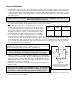
Tension Screw
Hinge Spring
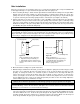
Tension Screw
Hinge Spring
Figure 3a:
Hinge orientation for gates which are:
hinged left and open towards you
hinged right and open away from you
Turn the nut clockwise to increase spring
tension.
Figure 3b:
Hinge orientation for gates which are:
hinged left and open away from you
hinged right and open towards you
Turn the nut counter-clockwise to
increase spring tension.
Post Mounting Plate
Post Mounting Plate