Allworx Px 6/2 Expander Installation Guide
No part of this publication may be reproduced, stored in a retrieval system, or transmitted, in any form or by any means, electronic, mechanical, photocopy, recording, or otherwise without the prior written permission of Allworx. © 2008 Allworx, a wholly owned subsidiary of PAETEC. All rights reserved. Allworx is a registered trademark of Allworx Corp. All other names may be trademarks or registered trademarks of their respective owners.
Px 6/2 Expander Installation Guide Table of Contents Installation Overview .................................................................................................................................. 1 Unpacking .................................................................................................................................................. 2 Chassis Views...................................................................................................................................
Px 6/2 Expander Installation Guide 1 Installation Overview Note: Use of the Allworx Px 6/2 Expander requires connection to an Allworx 6x, 10x, or 24x server. The server must be equipped with the Internet Call Access Feature Key. Procure the key before beginning installation at the customer site. Steps for procuring the key are included in Section 7, Procuring and Installing the Internet Call Access Feature Key. Installation of the Allworx Px 6/2 Expander involves the following steps: 1. Unpacking 2.
Px 6/2 Expander Installation Guide 2 Unpacking Open the box and carefully unpack it. Save all shipping and packaging materials. Verify all items against the parts list shown in Table 1. If any items are missing, contact your dealer or Allworx Customer Support at 866255-9679.
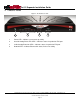
Px 6/2 Expander Installation Guide 3 Chassis Views Figure 1: Front Chassis View 1 2 3 4 1 Power LED – Indicates system start-up activity 2 3 Outside Analog Phone Line LEDs – Indicates status of a particular FXO port Inside Analog Extension LEDs – Indicates status of a particular FXS port 4 Network LED – Indicates Ethernet link status; flashes for activity 300 Main Street • East Rochester, NY 14445 • Toll Free 1-866-ALLWORX • 585-421-3850 • www.allworx.com © 2008 Allworx.
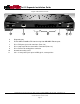
Px 6/2 Expander Installation Guide Figure 2: Rear Chassis View 5 6 7 8 9 5 Diagnostic port 6 7 RJ-45 10BaseT/100BaseTX Auto-Sensing Auto-MDI/MDIX Ethernet port. RJ-11 FXS ports for inside extensions (Ports 7-8) 8 RJ-11 loop-start FXO for central office connection (Ports 1-6) 9 RJ-11 Power Fail analog phone connector 10 11 Ground connecting screw 5.5 x 2.1 mm power jack.
Px 6/2 Expander Installation Guide 4 Mechanical 4.1 Tabletop or Shelf Placement To install the Allworx Px 6/2 on a tabletop or shelf: 1. Remove the four rubber feet from the packaging. 2. Turn over the chassis and notice the triangle on each corner (2 large triangles in front, 2 smaller in back). 3. Remove the paper backing from each rubber foot and place one foot in each triangle. 4.2 Wall Mount To mount the Allworx Px 6/2 on ½” drywall: 1.
Px 6/2 Expander Installation Guide Figure 3: Wall Mount Orientation Correct Orientation Wrong Orientation 300 Main Street • East Rochester, NY 14445 • Toll Free 1-866-ALLWORX • 585-421-3850 • www.allworx.com © 2008 Allworx. All rights reserved Version 04.
Px 6/2 Expander Installation Guide 5 Electrical 5.1 Chassis Ground Warning: Failure to follow these steps may result in equipment damage, personal injury, and void the product warranty. To help prevent electrical shock, the separate, protective earthing terminal located next to the power jack on the rear panel (See Figure 2 item 10) must be permanently connected to earth using 18 AWG wire or larger. 5.2 Power-Up Sequence Connect the unit’s Network port to an Allworx server LAN.
Px 6/2 Expander Installation Guide 6 Diagnostic Port The Diagnostic connector (See Figure 2, Item 5) is a serial port. Should Allworx Customer Support instruct you to capture diagnostic data, connect a null modem serial cable from the Diagnostic connector to the serial port on a PC.
Px 6/2 Expander Installation Guide 7 Procuring and Installing the Internet Call Access Feature Key Note: Use of the Allworx Px 6/2 Expander requires connection to an Allworx 6x, 10x, or 24x server. The server must be running Release 6.9 or higher and must have the Internet Call Access Feature Key. Obtain the key using the following procedure: 1. Update the server to Release 6.9 or higher, if it has not already been upgraded. 2. Submit a request for the Internet Call Access key.
Px 6/2 Expander Installation Guide 8 Port Expander Configuration Much like an Allworx phone, the Port Expander gets its configuration information and software updates from the Allworx server. Therefore, the Network port of the Allworx Px 6/2 Expander must be attached either directly or remotely to an Allworx server. This is usually done by connecting to the server LAN through a network switch. Up to three Port Expanders can be connected to a given server.
Px 6/2 Expander Installation Guide take as long as five (5) minutes. It is now ready for CO lines and analog phones to be connected to its FXO and FXS ports. 5. If the Power LED does not shine solid green within five (5) minutes. Unplug the Port Expander’s power adapter, wait five seconds, then plug it back in. 6. Activate the FXO and FXS ports through the Web Admin page on the Allworx Server. Refer to the Allworx System Administrator’s Guide, Release 6.9.2.
Px 6/2 Expander Installation Guide 8.2 Remote Connection Allworx Px 6/2 Expanders can be configured to run at sites that are remote to the Allworx server. Much like with a remote Allworx phone, this requires manual configuration of the Port Expander. The Boot Server IP (the Allworx Server’s IP) and the server’s Plug and Play Secret Key must be entered within the Port Expander’s configuration interface. In addition, forwarding of ports through intervening firewalls may be required.
Px 6/2 Expander Installation Guide 11. If you have entered a new password, save it for future reference. If the password is lost or forgotten, it can be reset by repeating the procedure in Section 8.3, Configuring the Port Expander Password and entering a new password. 12. Activate the FXO and FXS ports through the Web Admin page on the Allworx Server. Refer to the Allworx System Administrator’s Guide for Release 6.9 or higher for information on configuring the ports. 8.
Px 6/2 Expander Installation Guide The Port Expander’s analog phone connections can be used to connect Central Office (CO) lines or telephone handsets. The following table describes the ports: RJ-11 Ports Type 1-6 FXO (loop-start) 7-8 FXS Description Used to connect to Central Office (CO) lines Analog telephone handsets Table 3: Analog Telephony Ports It is recommended that the ports be connected as follows: • CO Lines: Begin with port 1 and move up.
Px 6/2 Expander Installation Guide 10 Data Network Connection The Network port is 10BaseT/100BaseTX auto-sensing and auto-MDI/MDIX port. Once the Port Expander is powered up and in normal mode, the Network LED indicates the state of the Network link, as shown below.
Px 6/2 Expander Installation Guide 11 Physical and Environmental Specifications Dimensions (W x H x D) Weight (Base Model) Power Temperature Humidity 12.1 x 1.9 x 7.6 inches (30.8 x 4.8 x 19.3 cm) 3 lbs DC 12V, 1 Amp. 0° ~ 40° C 15% ~ 90% RH, Non-condensing Table 6: Physical and Environmental Specifications 300 Main Street • East Rochester, NY 14445 • Toll Free 1-866-ALLWORX • 585-421-3850 • www.allworx.com © 2008 Allworx. All rights reserved Version 04.
Px 6/2 Expander Installation Guide 12 Regulatory Notices 12.1 FCC Part 68 This equipment complies with Part 68 of FCC rules and the requirements adopted by ACTA. On the backside of this equipment is a label that contains, among other information, a product identifier in the format US: AAAEQ##TXXXX. If requested, provide this number to the telephone company.
Px 6/2 Expander Installation Guide Users should ensure for their own protection that the electrical ground connections of the power utility, telephone lines and internal metallic water pipe system, if present, are connected together. This precaution may be particularly important in rural areas. Caution: Users should not attempt to make such connections themselves, but should contact the appropriate electric inspection authority, or electrician, as appropriate.
Px 6/2 Expander Installation Guide You may also find helpful the following booklet, prepared by the FCC: "How to Identify and Resolve Radio-TV Interference Problems.” This booklet is available from the U.S. Government Printing Office, Washington D.C. 20402. Changes and Modifications not expressly approved by the manufacturer or registrant of this equipment can void your authority to operate this equipment under Federal Communications Commissions rules.
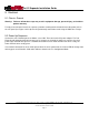
Px 6/2 Expander Installation Guide 13 Wall Mount Template 300 Main Street • East Rochester, NY 14445 • Toll Free 1-866-ALLWORX • 585-421-3850 • www.allworx.com © 2008 Allworx. All rights reserved Version 04.