
Owner Manual


EN
10
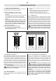
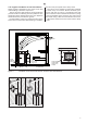
Figure 7. Opening the cover of the service hatch. Connections of the heater
B
A
1
1
2
3
4
2
Exemple d'installation,
pièces non fournies
A. Connection box
B. Connection cable
3.5. Electrical Connections
The heater may only be connected to the electrical
network in accordance with the current regulations
by an authorised, licensed professional electrician.
The wiring diagrams are included in the control
unit’s installation instruction.
Further instructions concerning exceptional installa-
tions can be obtained from local electrical authorities.
1. Remove heater from carton and place in
proper location in sauna room. Observe proper
clearances as per gures 3 and 5.
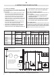
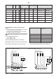
2. See applicable wiring diagram for heater
model (gure 6, see control unit manual
for detailed instructions how to connect the
heater and the control unit). Heater must
be permanently installed by using seal tight
conduit between the heater and the wall of the
sauna room (pigtails or plugs are not allowed
in the sauna room). Wiring must be done
by a licensed electrician, who must follow
wiring diagram provided and adhere to local
codes. Use proper AWG rated wire size and
use copper wire suitable for 194 °F (90 °C)
within sauna walls. Use grounding terminals
provided in sauna heater and control unit to
properly ground the equipment as per NEC
and local codes.
3. Inside the heater box there are two signs.
Please place the metal ”CAUTION” sign on
the interior wall of the sauna room directly
above the heater in a visible place (screws and
nails included). Place the metal ”WARNING”
sign outside, on the door of the sauna room.
”MAINTENANCE INSTRUCTIONS” are at the
end of this manual.
3.6. Installing the Heater
See gure 7.
• Connect cables to the heater.
• Place the heater and adjust the heater vertical-
ly straight using the adjustable legs.
3.7. Electric heater insulation resistance
When performing the nal inspection of the electri-
cal installations, a “leakage” may be detected when
measuring the heater’s insulation resistance. The
reason for this is that the insulating material of the
heating resistors has absorbed moisture from the
air (storage transport). After operating the heater
for a few times, the moisture will be removed from
the resistors.
Do not connect the power feed for the heater
through the RCD (residual current device)/GFI
(Ground Fault Interrupter)!
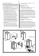
3.8. Replacing the Heating Elements
See gure 8.
3.9. Resetting the Overheat Protectors
If the temperature of the sauna room becomes
dangerously high, the overheat protector will
permanently cut off the supply of the heater. The
overheating protectors can be reset after the heater
has cooled down. See gure 9. Please check that the
stones are piled properly and the sensor is installed
according the installation instructions. See also the
installation instructions for control unit.