
Owner Manual


EN
9
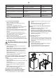
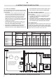
Table 3. Supply wires (from the power unit to the heater)
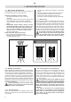
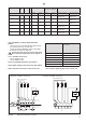
Figure 6. Electrical connections of heater
HL(S)7U1 / HL(S)9U1 / HL(S)11U1
140°C
T
L1 L2
A2A1
L3
R1 R2 R3
HL(S)7U3 / HL(S)9U3 / HL(S)11U3
1- Group
connections
L1
1
L2
1
A1 A2
L2
2
L1
2
140°C
T
L1
1
L2
1
A1 A2
L2
2
L1
2
2 - Group
connections
R3R2R1
208V 3-Phase heater
240V 1-Phase heater
Heater model Input
kW
Voltage Ph Amperage Min. 90 °C Copper
supply wire AWG No.
Suitable control units
1-Group
connection
2-Group
connection
1-Group
connection
2-Group
connection
1-Group connection 2-Group connection
HL(S)7U1 6,8 240 1 28,25 18,9 10 12
CX30-U1-U3 /
CX45-U1-U3
CX30-U1-U3 /
CX45-U1-U3
HL(S)9U1 9,0 240 1 37,5 25 8 10
CX45-U1-U3 CX30-U1-U3 /
CX45-U1-U3
HL(S)11U1 10,5 240 1 43,75 29,2 6 8
CX45-U1-U3 CX30-U1-U3 /
CX45-U1-U3
HL(S)7U3 6,8 208 3 18,8 n/a 12 n/a
CX30-U1-U3 /
CX45-U1-U3
n/a
HL(S)9U3 9,0 208 3 25 n/a 10 n/a
CX30-U1-U3 /
CX45-U1-U3
n/a
HL(S)11U3 10,5 208 3 29,2 n/a 8 n/a
CX30-U1-U3 /
CX45-U1-U3
n/a
Table 4. Heater grade setting of the control unit
Heater model Heater grade setting of the
control unit
HL(S)7U1 C2
HL(S)9U1 C2
HL(S)11U1 C1
HL(S)7U3 C2
HL(S)9U3 C2
HL(S)11U3 C1
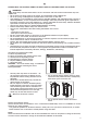
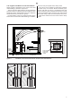
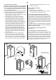
3.4. Installation of the Control Unit and
Sensor
• The control unit includes detailed instructions
for fastening the unit on the wall.
• Install the sensor (WX248), which comes with
the heater, as shown in gure 5.
Do not place the supply air vent so that the air
flow cools the temperature sensor. Figure 4.
3.4.1. Suitable control units
• Harvia CX30-U1-U3
• Harvia CX45-U1-U3
See more detailed information from table 3.
Heater grade setting of the control unit: See table 4.
Please read the instructions of the control unit.