Dunstesse AEF 3590 N AEF 3610 N
Contenuti - Contenents 1 - GENERALITÀ ..................................................................................... 5 2 - COMPONENTI ................................................................................... 5 3 - AVVERTENZE PER LA SICUREZZA ....................................................... 5 4 - INSTALLAZIONE ................................................................................ 6 4.1 - Scelta del tipo di installazione .......................................................
Sommaire - Inhalt 1 - GENERALITES ................................................................................. 25 2 - COMPOSANTS ................................................................................ 25 3 - INSTRUCTIONS POUR LA SECURITE .................................................. 25 4 - INSTALLATION ................................................................................ 26 4.1 - Choix du type d’installation ......................................................................
Part 1 - INSTALLATION INSTRUCTIONS 1 - GENERAL DATA This hood has been designed to be wall-mounted above a cooking hob with one side resting against a wall. It works either by suction (external outlet) or filter (internal recycling). Because of the complexity and weight of the hood, its installation should be carried out by qualified staff, taking care to respect all local regulations on air discharge. The manufacturer cannot be found liable for any damage due to improper installation.
Part 1 - INSTALLATION INSTRUCTIONS 3.8 - Before carring out any kind of maintenance or cleaning, disconnect the hood from the mains supply. 3.9 - If the room where the cooker hood is to be used contains a fuel burning appliance such as a central heating boiler then this must be of the room sealed or balanced flue type. If other types of flue or appliance are fitted ensure that there is an adequate supply of air into the room.
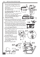
Part 1 - INSTALLATION INSTRUCTIONS 4.2 - Installation of the hood canopy C 1 - Drilling the wall a) Mark on the wall the centres of holes 1 for fixing of the hood canopy C. The centre of hole 2 for fixing the chimney, (fig. 5a) air outlet directed upwards or towards the wall, (fig. 5b-c) air outlet to the right or left hand side, must be marked at a distance X from the line between holes 1, obtained by measuring the extension Z of the chimney required for installation, plus 11 mm X=Z+18-7.
Part 1 - INSTALLATION INSTRUCTIONS 3 - Fitting the hood canopy C to the wall a) Remove the metal grease filters and the activated charcoal filter, if there is any (see the paragraph on Maintenance). b) Fit the support rod B using the two screws K (3,5x9,5) provided (fig. 8). c) Hook the hood canopy C to the eye bolts O fixed in holes 1 (fig. 9). d) Adjust the support rod B so that it pushes against the wall (fig. 10). 8 9 e) Adjusting position (fig. 11).
Part 1 - INSTALLATION INSTRUCTIONS 4.3 - Installation of the chimney A No matter which type of installation is being used, any wooden shelves in the area where the hood is to be fitted must first be removed, drilled and later replaced. 1 - Drilling the shelves: a) Using the cardboard template provided, and taking hole “B” as a point of reference, drill the shelves along the central axis to allow the passage of the chimney.
Part 1 - INSTALLATION INSTRUCTIONS - Remove the plug from the upper part of the ducting fan unit (fig. 17), as it is not possible to insert the flange F with the plug in place. - Fit the flange F Ø120 or 150 mm (fig. 18), replace the plug. · Air outlet directed to the right or left hand side (fig. 4a-b). - Remove the four screws fastening the plastic frame, as shown in fig. 16. - Fit the ducting spigot R (fig. 19) and replace the four screws removed as above.
Part 1 - INSTALLATION INSTRUCTIONS 4.4 - Ducting or recirculation fitting 25 1 - Ducting fitting. This is possible for all forms of installation: a) Connect the air outlet to the external ducting system. b) Remove the activated charcoal filter (if there is one) inside the hood canopy (see Maintenance). 2 - Recirculation fitting This is only possible with the air outlet directed upwards. Fit the venting grille G onto the air outlet (Fig. 25).
Part 2 - USE AND MAINTENANCE INSTRUCTIONS 1 - SAFETY WARNINGS 1.1 1.2 1.3 1.4 It is most important that all the warnings shown in paragraph 3 of the Installation Instructions are strictly observed. Moreover, pay special attention to the following warnings during the use and maintenance of the cooker hood: - The grease filters and charcoal filters should be cleaned or replaced as recommended by the manufacturer or more frequently if the hood is used consistently (over 4 hours per day).
Part 2 - USE AND MAINTENANCE INSTRUCTIONS 3.1 - Metal grease filters 1 - Cleaning These filters must be washed when LED 0/1 Motor starts to flash, or at the most once every 2 months, using a normal household detergent; their compact size also enables them to be washed in a dishwasher. 2 - Removing the filters Remove one filter at a time, supporting it from below and pulling back the stainless steel handle (fig.29 ). Replace, making sure that the handle is still facing towards the outside.
Part 2 - USE AND MAINTENANCE INSTRUCTIONS 2 - Replacing Remove the grease filters and take out the activated charcoal filter from its housing, turning the lugs provided (fig. 30). Insert the new activated charcoal filter and replace the metal grease filters.
Dir.