Dunstesse AEF 3850 X
Dear Customer, If you follow the recommendations contained in this Instruction Manual, your appliance will give you constant high performance and will remain efficient for many years to come.
RECOMMENDATIONS AND SUGGESTIONS INSTALLATION • The manufacturer will not be held liable for any damages resulting from incorrect or improper installation. • The minimum safety distance between the cooker top and the extractor hood is 650 mm. • Check that the mains voltage corresponds to that indicated on the rating plate fixed to the inside of the hood. • For Class I appliances, check that the domestic power supply guarantees adequate earthing.
CHARACTERISTICS Dimensions GB 14
Components 15 Ref. 1 14.1 12a 7.2.1 14 9 2.1 11 2 2.1 2.2 8a 8b 9 14 14.1 15 12c Q.ty Product Components 1 Hood Body, complete with: Controls, Light, Blower, Filters 1 Telescopic Chimney comprising: 1 Upper Section 1 Lower Section 1 Right Air Outlet Grill 1 Left Air Outlet Grill 1 Reducer Flange ø 150-120 mm 1 Hood Body Air Outlet Extension Piece consisting of two Half Shells 2 Air Outlet Connection Extension 1 Air Outlet Connection 2 8b 2.2 Ref. Q.ty Installation Components 7.2.
INSTALLATION 1÷2 Wall drilling and bracket fixing 650 min. 12a 116 116 305 11 X 7.2.1 Wall marking: • Draw a vertical line on the supporting wall up to the ceiling, or as high as practical, at the centre of the area in which the hood will be installed. • Draw a horizontal line at 650 mm above the hob. • Place bracket 7.2.1 on the wall as shown about 1-2 mm from the ceiling or upper limit aligning the centre (notch) with the vertical reference line.
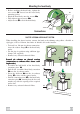
Mounting the hood body • Before attaching the hood body, tighten the two screws Vr located on the hood body mounting points. • Hook the hood body onto the screws 12a • Fully tighten support screws 12a • Adjust screws Vr to level the hood body. Vr 12a Connections DUCTED VERSION AIR EXHAUST SYSTEM When installing the ducted version, connect the hood to the chimney using either a flexible or rigid pipe ø 150 or 120 mm, the choice of which is left to the installer.
RECIRCULATION VERSION AIR OUTLET Assemble the two halves of the hood body extension piece 14. Push fit the assembled hood body extension piece 14 onto the air outlet. Push fit connection 15 onto the hood body extension piece 14. Insert the connection extension pieces laterally 14.1 in connection 15. 15 • Make sure that the outlet of the extension 14.1 pieces is horizontally and vertically 8b aligned with the chimney outlets.
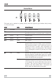
USE Control Panel S1 I F 2 L T1 T2 3 4 T3 T4 The hood can be switched on pushing directly onto the requested speed without firstly having to select 0/1 button. KEY LED L 0/1 Light T1 0/1 Motor FUNCTIONS Turns lighting on and off. First speed. When pressed for about 2 seconds the motor is switched off. T2 Speed on Second speed. T3 Speed on Third speed. T4 Speed Fixed Max. speed Flashing Intensive speed. Suitable for the strongest cooking vapours and odours.
MAINTENANCE Grease filters CLEANING METAL SELF- SUPPORTING GREASE FILTERS Alarm signal reset • Switch off the lights and extractor motor. • Press button T3 for at least 3 seconds, until the leds start to flash. Cleaning the filters • The filters must be cleaned every 2 months of operation, or more frequently for particularly heavy usage, and can be washed in a dishwasher. • Remove the filters by releasing the fixing hooks. • Wash the filters, taking care not to bend them. Allow them to dry before refitting.
• The filter is not washable and cannot be regenerated. It must be replaced when led S1 flashes or at least every 4 months. The alarm signal will only light up when the extractor motor is switched on. Alarm signal reset • Switch off the lights and extractor motor. • Press button T3 for at least 3 seconds, until the leds start to flash.
Dir.