Installation and Servicing Instructions Alpha C23/27 Range of Wall Mounted, Fan Assisted, Room Sealed, Gas Fired Combination Boilers For Technical help or for Service call ... ALPHA HELPLINE Tel: 0870 3001964 Nepicar House, London Road, Wrotham Heath, Sevenoaks, Kent TN15 7RS Service Listed Alpha C23 Alpha C27 G.C. No. 47 532 22 G.C. No.
CONTENTS 1 2 3 4 5 6 Introduction ....................................... 2 Technical data ................................... 3 General boiler information .................. 6 Installation ......................................... 10 Commissioning ................................. 15 Boiler operation ................................. 17 1 7 8 9 10 11 12 Routine servicing ............................... 18 Component replacement ................... 20 Wiring diagrams ................................
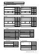
2 2.1 TECHNICAL DATA PERFORMANCE - NATURAL GAS Alpha C23 Alpha C27 Central Heating MAX. MIN. Heat Input (Gross) kW Btu/h 28.5 97 200 12.3 42 000 Heat Output (modulating) kW Btu/h 23.3 79 500 9.3 31 700 Burner Pressure mbar in wg 10.9 4.36 2.3 0.9 m³/h ft³/h 2.71 95.70 1.16 40.96 Settings Room sealed chamber panel fitted Gas Rate Alpha C23 Central Heating Heat Input kW (Gross) Heat Output (modulating) Btu/h kW 112 600 48 800 27.0 11.0 Burner Pressure Btu/h mbar 92 100 11.
2.5 GENERAL 2.6 ELECTRICAL Case Dimensions Height 720 mm Supply (without bottom tray) Width Depth 450 mm 330 mm External Fuse Power Consumption 3A 170 W C23 22 mm 1.6 L Internal Fuse Ignition Electrode Spark Gap F2 A 3 mm 1.8 L 100 mm Flame Sensing Electrode Gap 6 mm Air Duct Diameter Flue Duct Diameter 60 mm Gas Connection Primary Water Content C27 2.7 230/240 V ~ 50 Hz FLUE LENGTHS Flue length = 0.
2.
3 3.1 GENERAL BOILER INFORMATION GAS SUPPLY The Alpha C23 boiler requires a gas rate of 2.71 m³/h (95.7 ft³/h) and the Alpha C27 a gas rate of 3.14 m³/h (110.9 ft³/h). The meter and supply pipes must be capable of delivering this quantity of gas in addition to the demand from any other appliances in the house. The boiler requires at least a 22 mm gas supply pipe. The complete installation, including the meter, must be tested for gas soundness and purged as described in BS 6891. 3.
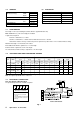
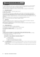
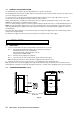
HORIZONTAL FLUE OPTIONS - Lmax = 3 metres L = B + C + 185 mm L = B + C + E + 185 mm B C B C E B F E C L = B + E + F + 185 mm + (90° bend = 1 metre) B L = B + C + 185 mm + (2 x 45° bends = 1 metre) VERTICAL FLUE OPTIONS Fig.
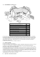
3.5 FLUE TERMINAL LOCATION - Fig. 4 Fig. 4 Terminal position Min. distance A Directly below an opening, air brick, windows, etc.
3.7 CENTRAL HEATING SYSTEM - Fig. 5 The boiler is designed for use in a sealed central heating system in accordance with the requirements of BS 5449 and BS 6798. The system should be designed to operate with flow temperatures of up to 82°C. When designing the system, the pump head, expansion vessel size, mean radiator temperature, etc. must all be taken into account. Refer to the pump performance table for guidelines.
3.9 DOMESTIC HOT WATER SYSTEM The minimum flow rate needed for the flow switch and burner to operate is 2.0 litres/min. The incoming mains water pressure should be between 0.2 and 8 bar to ensure efficient operation. If the pressure is above 7 bar a pressure reducing valve must be fitted. To ensure economic use, the pipe runs between the boiler and taps should be in 15 mm copper pipe and be as short as possible. Where possible the pipework should be insulated to reduce heat loss.
4.3 PREPARE THE WALL - Figs. 9, 10 1. Decide upon the position of the boiler taking into account the clearances required for servicing and the flue terminal position. 2. Tape the template to the wall (ensure it is level and the right way up) and mark the position of the holes for the boiler mounting bracket and bottom fixings. If rear exit flue is used, mark the position of the hole for the flue. 3.
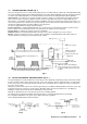
F G H A - Heating flow (22 mm) B - Hot water outlet (15 mm) C - Gas inlet (22 mm) I D - Cold water mains inlet (15 mm) E - Heating return (22 mm) F - Pressure relief valve (15 mm) G - Heating drain point H - Cold water inlet filter I - By-pass 20 23 70 70 C 95 B 95 D 70 E 50 A Fig. 11 4.6 1. FIT THE FLUE - Figs. 12, 13 The following procedure applies to both rear or side exit flue. The only difference being the lengths to which the ducts are cut.
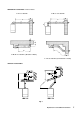
4.7 FIT A FLUE EXTENSION - Figs. 12, 13 Note: 1. The maximum horizontal flue assembly length must not exceed a length of 3 metres. 2. If the flue is more than 1.5 m, the restrictor must be removed from the boiler flue adaptor (see Fig. 13). 1. Withdraw the inner flue duct from the outer air duct supplied with the boiler. 2. Withdraw the inner flue duct from the extension.
Fig. 13 - Side flue 4.8 CONNECT THE MAINS SUPPLY - Fig. 14 1. Gain access to the boiler terminal block by releasing the two fixing screws (one each side) securing the control panel and lowering the panel. Refer to Technical Data, section 2.9 for connection details. 2. Note: This boiler has been fitted with a mains supply cable.
Fig. 15 5 COMMISSIONING When commissioning the boiler, ensure the Benchmark Log Book is completed. 5.1 FILL THE SYSTEM 1. The boiler is fitted with an automatic air vent positioned on the pump (see Fig. 2). The vent is always open and has no sealing cap. 2. Open the central heating flow and return valves (slot in-line with valve) (see Fig. 11). 3. Open the fill point valve on the filling loop until water is heard to flow. To aid venting, the boiler drain point (see Fig.
5.3 TEST FOR GAS SOUNDNESS AND PURGE THE SUPPLY 1. With the boiler gas service cock closed (slot at right angles to valve). Pressure test the gas supply and inlet pipework connection to the boiler gas service cock for soundness in accordance with BS 6891. 2. Loosen the gas inlet pressure test point screw on the gas valve (see Fig. 17). Ensure the gas supply is on and open the boiler service cock to purge in accordance with BS 6891. 3. Retighten the test point screw and test for gas soundness.
5.7 1. 2. 3. 4. 5. FINAL ASSEMBLY Raise the control panel and secure in position with the screws provided. If the boiler is to be left in service with the User, set the controls, clock (if fitted, see User's Operating manual) and room thermostat (if fitted) to the User's requirements. If the boiler is not to be handed over immediately, close the boiler gas service cock and switch off the electrical supply.
6.3 FROST THERMOSTAT The boiler incorporates a built in frost thermostat which automatically turns on the boiler and pump if the water in the boiler falls below 8°C, providing the electrical supply is on. The boiler will operate until the water temperature in the system reaches approximately 40°C. 6.4 PUMP If the electrical supply is on and the boiler has not operated for 24 hours for heating or hot water, the pump will operate automatically for five minutes every 24 hours. 6.
Combustion chamber front cover Room sealed chamber panel screws Ignition electrode (front) Flame sensing electrode (rear) Fig. 18 7.2 PREPARE FOR SERVICING - Fig. 18 1. Ensure the electrical supply is isolated and the gas supply is off. 2. Unscrew the two screws securing the control panel and lower the panel. 3. Lift the case front panel upwards slightly and pull it forwards to remove it from the boiler. 4.
8 COMPONENT REPLACEMENT It is the law that any service work must be carried out by a competent person, i.e. CORGI registered personnel. Warning: Before replacing any boiler components, isolate the electrical supply and close the boiler gas service cock. Allow the boiler to cool. Always test for gas soundness after replacing any gas carrying components or disturbing any gas connections. Check the operation of the boiler. (Refer to Boiler Operation, section 6).
Flame sensing electrode (rear) Ignition electrode (front) 6 mm 3 mm Fig. 19 8.5 MAIN BURNER 1. Remove the burner as described in Routine Servicing, section 7.2. 2. Re-assemble with a new burner as described in Routine Servicing, section 7.4. 8.6 BURNER INJECTORS 1. Remove the burner as described in Routine Servicing, section 7.2. 2. Unscrew the damaged injector and screw in a replacement. 3. Re-assemble as described in Routine Servicing, section 7.4. 8.7 FAN - Fig. 20 1.
Air pressure switch Fan Primary temperature sensor Clip Overheat thermostat Fig. 20 8.10 GAS VALVE - Fig. 21 1. Gain access behind the casing as in section 8.1. 2. Disconnect the coil wires and pressure tube from the gas valve. 3. Loosen the one screw (see Fig. 21) securing the electrical plug and disconnect the plug. 4. Disconnect the burner manifold union and the gas inlet pipe union from the manifold. 5. Remove the two manifold screws from beneath the boiler. 6.
8.12 INTERNAL FUSE - Refer to Fig. 14 The fuse is located in the boiler terminal block. 1. Gain access as described in Installation, section 4.8. 2. Lift out the fuse holder and remove the fuse. Fit a fast blow 2 A fuse as a replacement, ensuring that the holder snaps into position. 3. Re-assemble in reverse order, ensuring the terminal block is located correctly on the plastic pins. 8.13 PCB - Fig. 22 1. Gain access behind the control panel as described in section 8.1. 2.
8.17 COMBUSTION CHAMBER INSULATION 1. Gain access to the combustion chamber as described in section 8.1. 2. The front panel slides out. 3. To replace the rear and side panels remove the heat exchanger as described in section 8.16. Prise out the top of the rear insulation panel and lift it up and out of the boiler, then slide out the side insulation panels. 4. Fit a new panel and re-assemble in reverse order. 5. Refill and pressurise the system. (Refer to Commissioning, section 5.1). 8.
Primary pressure switch Pump DHW sensor Pressure relief valve Fig. 25 Complete pump 1. Remove the pump head as described above. 2. Unscrew the automatic air vent from the pump outlet. 3. Disconnect the pump unions and withdraw the pump body. 4. Connect the wiring as described above, ensure that pump is set to maximum and re-assemble using new sealing washers. 5. Refill and pressurise the system. (Refer to Commissioning, section 5.1). 8.22 PRIMARY PRESSURE SWITCH - Fig. 25 1.
8.25 MAINS WATER INLET FILTER - Fig. 11 1. Drain the boiler hot water circuit as described in section 8.2. Remove the four screws securing the bottom tray and remove the tray. 2. Withdraw the filter after disconnecting the unions between the inlet valve and boiler (item H in Fig. 11). 3. Clean or replace and re-assemble in reverse order. 8.
9 9.
9.
10 FAULT FINDING 10.1 CARRY OUT INITIAL FAULT FINDING CHECKS 1. Check that gas, water and electrical supplies are available at the boiler. i.e. Inlet gas pressure = 20 mbar Electrical supply = 230/240 V ~ 50 Hz CH water system pressurised to between 0.75 and 1.25 bar DHW flow rate is more than 2.5 litre/min 2. Carry out electrical system checks, i.e. Earth Continuity, Resistance to Earth, Short Circuit and Polarity with a suitable meter.
10.
10.
10.
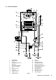
11 SHORT PARTS LIST Reference Fig. 2, item 7 Fig. 2, item 7 Description Burner assembly (C23) Burner assembly (C27) Main injector 1.30 mm (C23) Main injector 1.30 mm (C27) Fig. 2, item 8 Fig. 2, item 8 Primary heat exchanger (C23) Primary heat exchanger (C27) Fig. 21 Fig. 25 Gas valve - Honeywell VK4105M5009 Pump Fig. 20 Fig. 20 Fan assembly Air pressure switch (C23) Fig.20 Fig. 25 Air pressure switch (C27) Primary pressure switch Fig. 2, item 1 Fig.
12 SERVICE HISTORY DETAILS OF BOILER INSTALLATION Date of Installation: ...................................................................... Name of Installer: ......................................................................... Address: ...................................................................................... .................................................................................................... ...............................................................................
Alpha C23/27 35
Alpha Therm Limited. Nepicar House, London Road, Wrotham Heath, Sevenoaks, Kent TN15 7RS Tel: 0870 3001 964 These instructions have been carefully prepared but we reserve the right to alter the specification at any time in the interest of product improvement. © Alpha Therm Limited 2003. email: info@alphatherm.co.uk website: www.alpha-innovation.co.uk Manual compiled and designed by Publications 2000 - Tel: (01670) 356211 Part No. 1.