
Instruction manual


Page 6 Narrow to Wide SCSI Upgrade Instructions
PDI-00440-70, Rev. A01
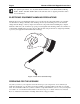
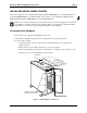
Removing the 50-Pin SCSI Cable
Observe the routing of the existing SCSI cable before you remove it—you will route the Wide
SCSI cable along the same path.
1. Remove the bail mount clips for the external narrow SCSI connector from the rear panel.
Do not remove any cables other than the SCSI cable.
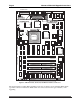
2. Unplug the 50-pin SCSI cable from P2 on the AM-176 board.
3. Unplug the 50-pin SCSI cable from all SCSI peripherals and remove the cable. Also remove any
adapters being used to attach Wide SCSI devices to the narrow cable.
Installing the 68-pin Wide SCSI Bus Cable
1. Plug the 68-pin Wide SCSI interface into P5 on the AM-176 board.
2. Route the Wide SCSI cable to the SCSI peripherals and out to the external SCSI cutout on the
rear panel. Plug the cable into each disk or tape drive.
If you are connecting narrow SCSI devices to a Wide SCSI cable, be sure to use the
appropriate adapter between the device and the cable connector.
3. Mount the new Wide SCSI cable/adapter plate assembly onto the existing SCSI cutout on the
rear panel, using the standoffs provided with your upgrade kit.
4. Make sure the Wide SCSI cable is terminated properly. This normally means plugging an
external active terminator (PRA-00222-20) into the external Wide SCSI port on the rear panel.
This terminator is included in your upgrade kit. Fasten the thumbscrews into the standoffs to
secure the terminator. See Appendix A for more information about SCSI bus termination.
5. If you are adding a disk or tape drive, don’t forget to attach the DC power cables from the power
supply to it. Refer to your computer’s service manual for peripheral installation instructions.
Finishing Up
After completing the upgrade, remember to enable Wide SCSI operation on your system. Refer to
your computer’s owner’s manual for more information on enabling Wide SCSI operation.
You have completed the upgrade. Boot and test your system before replacing the computer's cover, in
case you need to make some adjustments. Refer to your computer’s owner’s manual for more
information on testing procedures.
Once your system completes the testing procedures successfully, replace the top cover and fasten with
the four original screws.