
Installation guide

Page 4 Installation Instructions: AM-3501 Expansion Subsystem
3.0INSTALLATION PRECAUTIONS
To avoid damaging static sensitive electronic components, make sure you are properly
grounded and using a work area suitable for working on electronic equipment. Although
it doesn’t seem like much, that tiny bolt of static electricity discharged through your
finger tips has the power to degrade or ruin electronic components.
Termination:
Two SCSI connectors are present on the rear panel of the AM-3501 subsystem. One
connector should be cabled back to the host computer. The other connector should
have an external SCSI terminator installed, or be connected to yet another external
SCSI device. Make sure that each
physical
end of the SCSI bus is properly terminated.
All other SCSI devices in between, in both the host computer and the subsystem,
should have their terminators removed.
See Appendix A at the end of this document which includes more detailed information
about terminating SCSI peripherals and supplying termination power to the SCSI bus.
This information includes the standard Alpha Micro termination procedure for SCSI
peripherals used in AMOS based computers and subsystems.
The installation instructions pertaining to each SCSI peripheral also contains information
on how to configure terminators and termination power jumpers.
Device Address:
SCSI devices daisy-chained to a common bus must be configured so that none of the
devices share the same address.
4.0INSTALLATION OVERVIEW
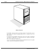
Your AM-3501 subsystem is assembled at the factory. Any peripheral devices or I/O
paddle cards you order with your AM-3501 will be installed and tested prior to shipment.
However, once you start using your subsystem, you may decide to add extra peripheral
devices or additional I/O boards. The instructions in the following sections describe the
procedure for opening the subsystem, followed by information for installing I/O boards
and SCSI peripheral devices (including magnetic tape, and hard disk drives).
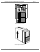
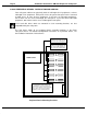
4.1Removing the Top Cover
When adding additional equipment or servicing your subsystem, it will be necessary to
remove the chassis top cover. The top cover is held in place with four phillips-head
screws located along the computer’s rear panel. To remove the top cover, remove all
four screws from the locations indicated in the following illustration. Once the screws
have been removed, the top cover can be slid back and removed.
PDI-03501-00, Rev. A00