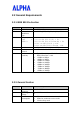
Installation Guide For WMP-D18 IEEE 802.
申請DGT使用手冊必須包含之資訊: 經型式認證合格之低功率射頻電機,非經許可,公司、商號或使用者均不得擅自 變更頻率、加大功率或變更原設計之特性及功能。 低功率射頻電機之使用不得影響飛航安全及干擾合法通信;經發現有干擾現象 時,應立即停用,並改善至無干擾時方得繼續使用。 前項合法通信,指依電信法規定作業之無線電通信。 低功率射頻電機須忍受合法通信或工業、科學及醫療用電波輻射性電機設備之干 擾。 在5.25~5.35秭赫(GHz)頻帶內操作之無線資訊傳輸設備,限於室內使用。 Federal Communication Commission Interference Statement This equipment has been tested and found to comply with the limits for a Class B digital device, pursuant to Part 15 of the FCC Rules.
- Reorient or relocate the receiving antenna. - Increase the separation between the equipment and receiver. - Connect the equipment into an outlet on a circuit different from that to which the receiver is connected. - Consult the dealer or an experienced radio/TV technician for help. This device complies with Part 15 of the FCC Rules.
in public retail store is prohibited. 2) Professional installer must carefully consult the professional installation manual and program the conducted output power no more than tested maximum conducted power for each antenna as documented in the manual 3) The antenna of end product must be installed so that at least 20 cm is maintained between the antenna and users, and 4) The transmitter module may not be co-located with any other transmitter or antenna.
the antenna used for this transmitter must be installed to provide a separation distance of at least 20 cm from all persons and must not be co-located or operating in conjunction with any other antenna or transmitter. (b) Manual must include tested maximum compliance eirp power as documented in the manual and FCC filling for each supplied antenna. (c) Warning to the installer that final eirp radiated power must adjusted to lower or equal to tested maximum eirp as documented in the manual.
Because high power radars are allocated as primary users (meaning they have priority) in 5250-5350 MHz, these radars could cause interference and/or damage to license exempt LAN devices. IMPORTANT NOTE: IC Radiation Exposure Statement: This equipment complies with Canada radiation exposure limits set forth for uncontrolled environments. This transmitter must not be co-located or operating in conjunction with any other antenna or transmitter. l 本產品將來在台灣販售時僅能使用 5GHz 頻段 Test Utility Installation: 1.
WinXP OS : Enter in the directory : C:\ ART_V52_build58\ art_driver\bin\XP\ Execute the inst_new_drv_xp.bat 2. Insert the adapter , then install the driver , the driver is located at Win2000 OS : C:\ ART_V52_build58\art_driver\bin\2000 WinXP OS : C:\ ART_V52_build58\ art_driver\bin\XP\ Configuration: 1. Enter the DOS command mode , then change the directory to : C:\ ART_V52_build58\art\bin\ 2. Input the instruction : art \id=2062 Then press enter . ART TEST MODE: 1.
2. Continuous Receive Options Continuous receive options will put the radio into receive mode to allow for radio measurements. Press ESC to return to the main Test Options menu when finished. 1.0 Scope 1.1 Document This document is to specify the product requirements for IEEE 802.11a MiniPCI Card. This Mini-PCI Card is based on Atheros AR5006X chipset that complied with IEEE 802.11a standard from 5.15~5.85GHz wideband.
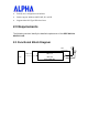
Ÿ Friendly user configuration and utilities Ÿ Drivers support Windows 98SE, ME, 2K, and XP Ÿ Supports Mini-PCI Type IIIB form factor 2.0 Requirements The following sections identify the detailed requirements of the IEEE 802.11a MiniPCI Card. 2.1 Functional Block Diagram UFL Connectors Mini-PCI PC 802.
2.2 General Requirements 2.2.1 IEEE 802.11a Section # Feature Detailed Description 2.2.1.1 2.2.1.2 Standard Radio and Modulation Type Frequency Range Channels Ÿ Ÿ 2.2.1.3 2.2.1.4 2.2.1.5 2.2.1.6 IEEE 802.11a BPSK, QPSK, 16QAM, 64QAM, OFDM 802.11a: & 5.15~5.25 GHz (FCC/IC/CE) .4 Chs 5.25~5.35 GHz (FCC/IC/Taiwan/CE) 4 Chs 5.470~5.725 GHz (FCC/CE ).11Chs 5.725~5.850 GHz (FCC/IC/Taiwan) .
2.2.3.4 2.2.3.
2.3 Software Requirements The Configuration Software supports Microsoft Windows 98SE, ME, 2000, and XP. This configuration software includes the following functions: Ÿ Information Information allows you to monitor network status. Ÿ Configuration Configuration allows you to configure parameters for wireless networking. Ÿ Security Supports enhanced security WEP, 802.1x,WPA,WPA2. 2.3.1 Information # Detailed Description 2.3.1.1 Feature General Information 2.3.1.2 Current Link Information Ÿ 2.3.1.
# 2.3.2.5 2.3.2.6 2.3.2.7 Feature Detailed Description Fragment Threshold Transmission Speed Ÿ Roaming Ÿ Ÿ boundary for messages Set the number of bytes used for RTS/CTS boundary This indicates the communication rates. Select appropriate transmission speed to match your wireless LAN settings Support Automatic or Manual Rescan to associate with access point. 2.3.3 Security # Feature Detailed Description 2.3.3.1 Encryption Ÿ Ÿ Ÿ 2.3.3.2 WEP Management Ÿ Ÿ 2.3.3.3 802.1x Ÿ Ÿ 2.3.3.
2.6 Requirements of Reliability, Maintainability and Quality # Feature Detailed Description 2.6.1 2.6.2 MTBF Maintainability Ÿ Ÿ 2.6.3 Quality Ÿ Mean Time Between Failure > 30,000 hours There is no scheduled preventive maintenance required The product quality is followed-up by ALPHA factory quality control system 2.7 Environmental Requirements # Feature Detailed Description 2.7.1 Operating Temperature Conditions Ÿ 2.7.2 Non-Operating Temperature Conditions Ÿ 2.7.
FCC ANTENNA USAGE AND TRANSMIT POWER To comply with FCC/Canada telecommunication regulation, the conducted output power of this transmitter, when use with each specific antenna supplied, cannot exceed the maximum limit indicated in the following tables. Wireless Mode Antenna Gain 802.11a SAA04-220080, 5dBi, Dipole Wireless Mode Antenna Gain 802.11a , SAA04-220080, 5dBi, Dipole Wireless Mode Antenna Gain 802.11a , SAA04-220080, 5dBi, Dipole Wireless Mode Antenna Gain 802.