User Manual For 802.11 b/g/n Draft 2.0 Intelligent NIC Card (Ralink RT3662) Model Number : WMP-N13 Revision: 1.2 This document contains confidential proprietary information and is the property of Alpha Networks Inc.. The contents of this document may not be disclosed to unauthorized persons without the written consent of Alpha Networks Inc..
Revision History Rev. Date Author Reason for Changes 1.0 1.1 1.
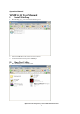
Operation Manual WMP-G15 Test Manual I. Install WinPcap 1. Run WinPcap_4_0_2.exe to install the WinPcap tool. 2. 3. Insert the WMP-N13 card and turn on the test board. Confirm the Ethernet link speed is 1000Mbps. II. 1. Run Test Utility Run “RT3882QA.exe” to start test tool.
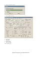
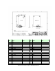
2. Select your Giga Ethernet adapter. 3. Start to TX/RX signal testing. a. Select channel. b. Select mode. c. Select data rate. d. Select bandwidth. e. Select TX/RX path. Start to transmit signal.
Contents 1.0 SCOPE........................................................................................................................................................................... 5 1.1 DOCUMENT ................................................................................................................................................................. 5 1.2 PRODUCT FEATURES ..........................................................................................................................
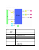
2.0 Requirements The following sections identify the detailed requirements of the 802.11n Draft 2.0 mPCI . 2.1 Functional Block Diagram 2.2 General Requirements 2.2.1 IEEE 802.11b Section # Feature Detailed Description 2.2.2.1 2.2.2.2 Standard Radio and Modulation Schemes Operating Frequency Channel Numbers IEEE 802.
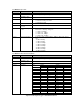
2.2.2 IEEE 802.11g Section # Feature Detailed Description 2.2.3.1 2.2.3.2 Standard Radio and Modulation Type Operating Frequency Channel Numbers IEEE 802.11g BPSK, QPSK, 16QAM, 64QAM with OFDM Data Rate Media Access Protocol Transmitter Output Power 2400 ~ 2483.5MHz ISM band 11 channels for United States 13 channels for Europe Countries 13 channels for Japan 6,9,12,18,24,36,48,54Mbps CSMA/CA with ACK 2.2.3.3 2.2.3.4 2.2.3.5 2.2.3.6 2.2.3.7 2.2.3.
# Feature Detailed Description 19 20 21 22 23 2.2.3.6 2.2.3.7 2.2.3.8 Media Access Protocol Transmitter Output Power at Antenna Connector 78 117 156 175.5 195 162 243 324 364.5 405 86.7 130 173.3 195 216.7 CSMA/CA with ACK Typical RF Output Power (tolerance +-2dB) at each RF chain, Data Rate and at room Temp. 25degree C Note: The maximum power setting will vary according to individual country regulations. Receiver Sensitivity at Antenna Connector 2.
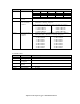
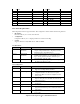
Pin Name 1 GND 3 GE_RXD3 5 3.3V 7 GE_RXD1 9 GND 11 GE_RXD2 13 3.
35 3.3V 37 GE_TXD0 39 GND 41 GE_TXCLK 43 GND 45 GE_TXD3 47 3.3V 49 GE_TXEN 51 GND P O P O P O P O P 36 GND 38 GND 40 NC 42 GND 44 NC 46 GND 48 iNIC_WLED 50 GND 52 iNIC_RST# P P P P O P I 2.4 Software Requirements The Configuration Software supports Linux2.6. This configuration software includes the following functions: Information Information allows you to monitor network status. Configuration Configuration allows you to configure parameters for wireless networking.
2.4.3 Security # Feature Detailed Description 2.4.3.1 Encryption 2.4.3.2 WEP Management 2.4.3.3 2.4.3.4 802.
Federal Communication Commission Interference Statement This equipment has been tested and found to comply with the limits for a Class B digital device, pursuant to Part 15 of the FCC Rules. These limits are designed to provide reasonable protection against harmful interference in a residential installation. This equipment generates, uses and can radiate radio frequency energy and, if not installed and used in accordance with the instructions, may cause harmful interference to radio communications.
This device is intended only for OEM integrators under the following conditions: 1) The antenna must be installed such that 20 cm is maintained between the antenna and users, and 2) The transmitter module may not be co-located with any other transmitter or antenna, 3) For all products market in US, OEM has to limit the operation channels in CH1 to CH11 for 2.4G band by supplied firmware programming tool. OEM shall not supply any tool or info to the end-user regarding to Regulatory Domain change.