
Instruction manual

4.0 Operation
4.1 Start-up and Test
4.1.1 AC Line Operation
Before making power supply connections, verify the correct voltage and 1.
frequency are available from the AC utility power source and voltage and
polarity from the DC battery system.
2.
the battery breaker on the power supply are off.
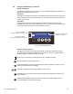
Plug the power cord into the convenience outlet and the battery cable into the 3.
inverter module. Plug the RTS into the temp probe connection and attach it to
the side of the center battery. Refer to Fig. 1-9. At this time, if an LRI is installed,
connect it to the front panel connector labeled LRI.
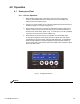
4.
alarm message appears in the Smart Display because the battery breaker is
while in this alarm state.
NOTE:
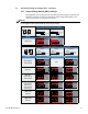
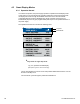
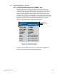
i2M OUT FREQ BAT IN
53
017-805-B0-010 Rev. K