AlphaNet™ DSM Series DOCSIS® Status Monitor Technical Manual Model XP-DSM Effective: June 2007 Alpha Technologies
Power Alpha Technologies ®
AlphaNet DSM Series DOCSIS Status Monitor Technical Manual 745-814-B0-001, Rev. A Effective Date: June, 2007 Copyright© 2007 Alpha Technologies, Inc. member of The GroupTM NOTE: Alpha denies responsibility for any damage or injury involving its enclosures, power supplies, generators, batteries or other hardware, manufactured by Alpha or members of the Alpha Group, when used for an unintended purpose, installed or operated in an unapproved manner, or improperly maintained.
Table of Contents Safety Notes............................................................................................................................... 7 1.0 Introduction...................................................................................................................... 8 2.0 System Overview............................................................................................................ 9 3.0 2.1 System Diagram.........................................................
6.3 SCTE-HMS MIB Alarms..................................................................................... 34 6.3.1 6.3.2 6.3.3 6.3.4 7.0 SCTE-HMS Configurable Alarms............................................................ 34 Distributing Alarm Settings...................................................................... 39 SNMP Traps............................................................................................ 41 General Power Supply Alarms...........................................
Figures Fig. 1-1, AlphaNet XP-DSM......................................................................................................8 Fig. 2-1, Single IP Mode.........................................................................................................10 Fig. 2-2, Dual IP Mode............................................................................................................10 Fig. 3-1, Location of MAC Addresses...........................................................................
Safety Notes Review the drawings and illustrations contained in this manual before proceeding. If there are any questions regarding the safe installation or operation of the system, contact Alpha Technologies or the nearest Alpha representative. Save this document for future reference. To reduce the risk of injury or death, and to ensure the continued safe operation of this product, the following symbols have been placed throughout this manual. Where these symbols appear, use extra care and attention.
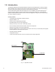
1.0 Introduction The AlphaNet DSM Series Embedded DOCSIS Transponder (XP-DSM) allows monitoring of Alpha XM2 and GMX power supplies through existing cable network infrastructure. Advanced networking services provide quick reporting and access to critical powering information. The XP-DSM utilizes Simple Network Management Protocol (SNMP) and standard Management Information Bases (MIBs) to provide network status monitoring and diagnostics.
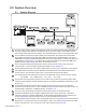
2.0 System Overview 2.1 System Diagram 10 MIB Browser 1 Power Supply 2 XP-DSM 4 5 Coax/HFC Network 6 CMTS TCP/IP Network ALM RDY COM LNK RF REG DS TMPR CTRL C O M E T H Battery Breaker N+1 OUTPUT 1B N+1 OUTPUT 2 LRI OUTPUT 1A C D Battery Input A B L O C A L Temp Probe 3 Local Computer 7 DHCP Server 8 TFTP Server 9 TOD Server 11 Web Browser 1 All power supply, battery, and generator data are stored in the class information base (CIB) tables in the power supply.
2.0 System Overview, continued 2.2 Single IP Mode vs. Dual IP Mode Overview The XP-DSM can operate in either Single (default) or Dual IP Mode. To switch the transponder from Single to Dual IP Mode the “Block CPE” function must be disabled in the Discrete Menu of the Alpha MIB (see Section 6.2). Single IP Mode In Single IP Mode all data from both the cable modem and power supply are accessed and managed through the modem’s IP address on the secure private modem network.
2.0 System Overview, continued 2.3 Network Connectivity Overview The XP-DSM cable modem must be recognized by the CMTS as a valid device to be assigned an IP address from the DHCP server, locate the TFTP and TOD servers, and communicate with the SNMP management server (trap receiver) (see Section 2.5). CMTS and system vendors use different security methods to insure network integrity, but common considerations are: 2.
2.0 System Overview, continued 2.5 XP-DSM Start-up and Reboot Routine TCP/IP Network TFTP Server Network Management System 6a TOD Server 6b DHCP Server MIB Browser Web Browser 6c Network Devices HFC Network CMTS 1 2 3 4 5 6 Cable Modem DSM Transponder 7 Local Laptop Time The above diagram, read left to right, indicates the order of operations as the transponder comes online.
2.0 System Overview, continued 2.5 6 XP-DSM Start-up and Reboot Routine, continued Monitoring and Managing Transponder and Power Supply Parameters. 6a A network management system (NMS) is software used to monitor transponder and power supply parameters on the network. The XP-DSM operates with an any NMS that supports SCTE-HMS standards. 6b The MIB browser is a valuable networking tool that enables personnel to remotely manage and configure an individual transponder through the SNMP-HMS and Alpha MIBs.
3.0 Network Configuration and Option Settings 3.1 Provisioning the DHCP Server with the MAC Addresses In the DHCP server, assign the cable modem’s RF MAC Address with a DOCSIS Configuration File to set modem communication options (see Section 3.2 to create a DOCSIS Configuration File). If desired, the MAC Address can be assigned a DSM Setup File to set transponder options (see Section 3.4). In Single IP Mode, if a DSM Setup File is not assigned, the transponder runs on its default settings (see Section 3.
3.0 Network Configuration, continued 3.2 The DOCSIS Configuration File A cable modem’s DOCSIS Configuration File is a type-length-value (TLV) file that contains important operational parameters as defined by the DOCSIS standards. It provides certain settings for the cable modem. In addition to standard entries, settings in the DOCSIS Configuration File should include the modem’s community strings and firmware upgrade parameters. Place the configuration file in the TFTP root directory.
3.0 Network Configuration, continued 3.2 The DOCSIS Configuration File, continued 3.2.2 Example DOCSIS Configuration File Example File Sets Read-Write Community string. Set the IP addresses and community strings to fit your system. SNMP SNMP SNMP SNMP SNMP MIB MIB MIB MIB MIB Object Object Object Object Object (11) (11) (11) (11) (11) [Len=21]:docsDevNmAccessStatus.1/4 [Len=21]:docsDevNmAccesslp.1/10.56.21.0 [Len=21]:docsDevNmAccesslpMask.1/255.255.255.0 [Len=25]:docsDevNmAccessCommunity.
3.0 Network Configuration, continued 3.3 Setting Communication Options The XP-DSM ships with the following default communication option settings: • Access Mode – Single IP • Network registration – DHCP • HTTP Web Server – Enabled • Read Community String – AlphaGet • Read/Write Community String – AlphaSet Communications Settings may be changed through the Alpha MIB remotely using a SNMP MIB browser, automatically using a DSM Setup File (see Section 3.
3.0 Network Configuration, continued 3.4 The DSM Setup File The DSM Setup File, atidoc01.cfg, is an optional type-length-value (TLV) formatted file similar to the modem’s DOCSIS Configuration File that distributes custom Alpha MIB settings to all XP-DSMs on a network. Unlike the DOCSIS Configuration File, the DSM Setup File is made up only of type 11 entries, OIDs supported by the transponder through the Alpha MIB.
3.0 Network Configuration, continued 3.4 The DSM Setup File, continued 3.4.2 Example of an atidoc01.cfg DSM Setup File Below is an example DSM Setup File with the following settings: Example DSM Setup File Parameters and Values Parameter Type Description Value atiMgmtSysDownloadCfgCheckProgress Integer OID: 1.3.6.1.4.1.926.1.3.2.1.12.0 Required file marker entry 3 atiMgntSnmpTrapAddress1 OID: 1.3.6.1.4.1.926.1.3.1.1. IP address Optional SNMP trap destination address 10.80.0.
3.0 Network Configuration, continued 3.4 The DSM Setup File, continued 3.4.3 Setting Transponder Community Strings with the DSM Setup File The default transponder read-only community string is AlphaGet. The default read-write community string is AlphaSet. These community strings are overridden by modem community strings set in the DOCSIS Configuration File. If the modem is left unsecured or if operating in Dual IP Mode, the XP-DSM needs to have its community strings set in the Alpha MIB.
3.0 Network Configuration, continued 3.5 Security in Dual IP Mode In Dual IP Mode additional SNMP security is required because data is exposed on the CPE network, which is more vulnerable to packet sniffing and community string deciphering than on the secure cable modem network. For an explanation of Dual IP Mode, see Section 2.2. For an explanation of the Alpha MIB, see Section 6.2. There are two methods of providing SNMP Security in Dual-IP Mode: the Secure Access List, and the Key-Match.
4.0 Using the Local Port The local port allows a technician to monitor and set XP-DSM parameter values directly using a personal computer and a Local Port Adapter Cable (Alpha Alpha P/N 745-826-21). Terminal emulation software is necessary (HyperTerminal is recommended). Procedure: 1. Launch the terminal emulation software. ALM RDY COM LNK RF REG DS TMPR CTRL C O M E T H Battery Breaker N+1 Serial Communication Settings Baud Data Bits Parity Stop Bits Flow Control OUTPUT 1B 3.
4.0 Using the Local Port, continued Text Table >tex TEXT ---------------------------------------------0 [ro] DHCP STATE : DISCOVER SENT 1 [ro] DHCP TIMER : 0 2 [ro] DHCP SERV : 0.0.0.0 3 [ro] DHCP SERV 54 : 0.0.0.0 4 [ro] DOWN STAT : 5 [rw] DOWN NAME 1 : 6 [rw] DOWN NAME 2 : 7 [rw] DOWN IP : 0.0.0.0 8 [rw] DOWN CFG : 9 [rw] DOWN CFG IP : 0.0.0.0 10 [rw] NTP SERV : 0.0.0.0 11 [ro] NTP DHCP : 0.0.0.0 12 [ro] NTP TIME UTC : 01/01/70 00:00:00 13 [ro] ENET ADDR : 00.90.EA.A0.1E.5F 14 [ro] IP ADDR IN USE : 0.0.
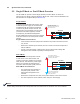
5.0 Upgrading Firmware 5.1 Upgrading XP-DSM Modem Firmware The firmware in the XP-DSM’s modem is upgraded using standard DOCSIS methods as defined in RFC2669 (available at http://www.faqs.org/rfcs/rfc2669.html). There are two ways to upgrade the modem’s firmware: by directly setting the appropriate MIB parameters in the docsDevSoftware branch, or by including the appropriate SNMP parameters and values in the modem’s DOCSIS Configuration File, stored on the TFTP root directory.
5.0 Upgrading Firmware, continued 5.1 Upgrading XP-DSM Modem Firmware, continued 5.1.3 Upgrading Modem Firmware Manually by Setting SNMP Parameters 1. Download the firmware and CVC files for your version modem from the Alpha Website. 2. Import the CVC into the modem’s DOCSIS Configuration File (to create a Configuration File, see Section 3.2). 3. Reset the modem. 4. Set the following MIB parameters using an SNMP MIB browser. Make reference to the table in Section 5.1.2.
5.0 Upgrading Firmware, continued 5.2 Upgrading XP-DSM Transponder Firmware There are three methods to upgrade XP-DSM firmware: manually setting SNMP parameters remotely in a MIB browser, setting them through the local port (see Section 4.0), and automatically in the DSM Setup File (to build a Setup File, see Section 3.4). Once the firmware download process has been initiated the XP-DSM will download the DSM firmware from the specified TFTP server.
5.0 Upgrading Firmware, continued 5.2 Upgrading XP-DSM Transponder Firmware, continued 5.2.1 Remotely Upgrading XP-DSM Firmware This section explains how to upgrade the XP-DSM firmware from version 1.08.0 to a more recent version by manually setting SNMP parameters. Firmware can also be upgraded automatically (see Section 5.2.2). Procedure: 1. Download the most recent firmware version from the Alpha Website and load it on the TFTP server. 2.
5.0 Upgrading Firmware, continued 5.2 Upgrading XP-DSM Transponder Firmware, continued 5.2.2 Upgrading XP-DSM Firmware Using a DSM Setup File, continued 3. Include in the atidoc01.cfg Setup File the following Alpha MIB parameters and values: Parameter Local Port Parameter Value atiMgmtSysDownloadReCfgTime [Counters] RECONFIG TIMER 0 (disable automatic upgrade) atiMgmtSysDownloadTftpAddress [Text] DOWN IP Address of TFTP server atiMgmtSysDownloadFile1 [Text] DOWN NAME 1 Firmware filename, e.g.
6.0 Data Management The XP-DSM remotely reports power supply data and alarms using the Simple Network Management Protocol (SNMP) over the DOCSIS (Data Over Cable Service Interface Specification) communication specification. The XP-DSM typically reports into a centralized Network Management System (NMS) through a standard collection of data access points referred to as the SCTE-HMS Management Information Bases (MIBs).
6.0 Data Management, continued 6.1 The SCTE-HMS MIB The SCTE-HMS MIB can be monitored with a SNMP compatible Network Management System (NMS) or with a MIB browser. The following MIB files are required for the MIB browser to collect data from the transponder. These files can be found on the Society of Cable Telecommunications (SCTE) Web site: www.scte.org. There are dependencies between MIB files, so they should be compiled in the following order.
6.0 Data Management, continued 6.1 The SCTE-HMS MIB, continued scteRoot (1.3.6.1.4.1.5591) scteHmsTree (1.3.6.1.4.1.5591.1) propertyIdent (1.3.6.1.4.1.5591.1.1) propertyTable (1.3.6.1.4.1.5591.1.1.1) Alarm thresholds for analog measurements currentAlarmTable (1.3.6.1.4.1.5591.1.1.2) Real-time view of items in alarm states as defined in the propertyTable and discretePropertyTable. discretePropertyTable (1.3.6.1.4.1.5591.1.1.3) SNMP alarm definitions for discrete parameters alarmsIdent (1.3.6.1.4.1.5591.1.
6.0 Data Management, continued 6.2 The Alpha MIB Measurements and settings for the power supply, generator, batteries, and XP-DSM are accessed using Simple Network Management Protocol (SNMP) through the Alpha Management Information Base (MIB). The Alpha MIB is defined through the SNMP MIB file ATI-TABLES-MGMT-MIB.mib, which can be obtained from the www.Alpha. com>Broadband>Status Monitoring>DSM>XP-DSM Tech. Support page. Many MIB browsers such as MG-Soft (www.mg-soft.
6.0 Data Management, continued 6.2 The Alpha MIB, continued The Alpha MIB hierarchy (see Section 10.0 for a list and definitions of all Alpha MIB parameters). enterprises (1.3.6.1.4.1) Alpha CIB Tables alphaTechInc (1.3.6.1.4.1.926.1) atiTables (1.3.6.1.4.1.926.1.2) atiCibTables (1.3.6.1.4.1.926.1.2.1) atiCibDiscTable (1.3.6.1.4.1.926.1.2.1.
6.0 Data Management, continued 6.3 SCTE-HMS MIB Alarms The HMS discrete and analog alarms provide the capability to monitor and alarm various power supply and environmental conditions and measurements. The alarms in the MIB tables can be defined and set to provide a custom monitoring system. 6.3.1 SCTE-HMS Configurable Alarms The SCTE-HMS MIB tables can be configured to send SNMP traps to a network management system in response to certain power supply conditions.
6.0 Data Management, continued 6.3 SCTE-HMS MIB Alarms, continued 6.3.
6.0 Data Management, continued 6.3 SCTE-HMS MIB Alarms, continued 6.3.1 SCTE-HMS Configurable Alarms, continued The following table displays the various analog alarms with common settings. Analog Alarms and Common Settings Analog Alarms psTotalStringVoltage 36V Description Alarm LOLO Enable LO HI HIHI Deadband Scaled representation of the full battery string in 1/100 Volts units 0x0F 3120 3140 4510 4530 .1V 0x0F 4160 4185 6015 6040 .
6.0 Data Management, continued 6.3 SCTE-HMS MIB Alarms, continued 6.3.1 SCTE-HMS Configurable Alarms, continued discretePropertyTable: Discrete Alarms This table holds the alarmable discrete objects that are passed from the power supply to the transponder. The SCTE-HMS-PS-MIB file defines all supported objects in this table, including the different states and dependencies of each object.
6.0 Data Management, continued 6.3 SCTE-HMS MIB Alarms, continued 6.3.
6.0 Data Management, continued 6.3 SCTE-HMS MIB Alarms, continued 6.3.2 Distributing Alarm Settings Alarm settings can be distributed automatically from one XP-DSM to another. They can also be distributed to all the XP-DSMs on a network by using a DSM Setup File. The procedure is a follows: STEP 1: Make the desired SCTE-HMS alarm settings on a master XP-DSM, according to the methods described in the sections above. STEP 2: Create an .s19 image file of the master XP-DSM’s alarm settings. To create an .
6.0 Data Management, continued 6.3 SCTE-HMS MIB Alarms, continued 6.3.2 Distributing Alarm Settings, continued The .s19 file should now look like the following: Save the file as “HMScfg.s19” and move it to a TFTP server on the network that is accessible by the XP-DSMs that you want to update. STEP 3: Distribute the .s19 file to other XP-DSMs. The .s19 file is distributed to other XP-DSMs by setting the following Alpha MIB parameters to the indicated values.
6.0 Data Management, continued 6.3 SCTE-HMS MIB Alarms, continued 6.3.3 SNMP Traps SNMP alarm traps sent by the XP-DSM are formatted according to the SCTE-HMSALARM-MIB specification with the following information included: SNMP Trap community string: commonTrapCommunityString, OID 1.3.6.1.4.1.5591.1.3.1.11.0 Example Alarm Trap The example below is a psTamper alarm trap indicating a discreteMinor alarm: tamper is open.
6.0 Data Management, continued 6.3 SCTE-HMS MIB Alarms, continued 6.3.2 SNMP Alarm Traps, continued Varbind Explanation Binding #1 commonPhysAddress OID: 1.3.6.1.4.1.5591.1.3.2.7.0 MAC Address of the transponder Binding #2 commonLogicalID OID: 1.3.6.1.4.1.5591.1.3.1.1.0 Optional user-configurable parameter that is often used to provide a unique logical name, or even the physical address of where the transponder is installed. Binding #3 alarmLogInformation OID: 1.3.6.1.4.1.5591.1.2.3.1.2.
6.0 Data Management, continued 6.3 SCTE-HMS MIB Alarms, continued 6.3.4 General Power Supply Alarms General power supply alarms are passed directly from the power supply to the transponder without specific definition and are classified in the HMS MIB table as psMinorAlarm and psMajorAlarm. There are a number of problems that can generate these alarms, and the exact nature of the situation is not specified.
7.0 Hardware Installation Before installing the hardware, provision the DHCP server with the cable modem’s RF MAC Address (see Section 3.1). If operating in Dual IP Mode, provision it with the CPE MAC Address as well. This allows the installation to be verified while the technician is on-site, eliminating the need for a second visit if there are problems with the installation. WARNING! To reduce the risk of electric shock, completely remove the inverter module from the power supply prior to installation.
7.0 Hardware Installation, continued 7.2 Hardware Installation Procedure NOTE: With the battery breaker in the OFF position, the power supply will not go into inverter mode. 1. Switch OFF the power supply’s battery breaker. 2. Unplug all inverter module connections (e.g. battery cable, remote temperature sensor). 3. Loosen the inverter module thumbscrews and slide the inverter module out just enough to disconnect the ribbon cable. Disconnect the ribbon cable. 4.
7.0 Hardware Installation, continued 7.2 Hardware Installation Procedure, continued 6. Locate the 18-pin jumper and insert the long side of the jumper firmly into the side of the inverter module. Inverter Module Fig. 7-2, The 18-pin Jumper Insert Long Side Into Inverter Module 7. Unpack the XP-DSM. If not yet done, record the MAC addresses from the front of the unit, and report it to the network manager for network provisioning (see Section 3.1). 8.
7.0 Hardware Installation, continued 7.3 XP-DSM Connections 7.3.1 Front Panel Diagram XP-DSM Front Panel CPE MAC Address Reset Button Status LEDs RF Connection Cable Modem Status LEDs Tamper Switch Connection AlphaBus Communication Port Battery String Connection (A/B) Local Port Connection RF MAC Address Fig. 7-4, Front Panel 7.3.2 Connecting the RF Drop CAUTION! Install a grounded surge suppressor (Alpha P/N 162-028-10 or equivalent). Connect the RF drop according to the diagram below.
7.0 Hardware Installation, continued 7.3 XP-DSM Connections, continued 7.3.3 Front Panel Connections XP-DSM Front Panel Connections ECM to SCM Interface (Alpha P/N 704-709-20) XM2 “Master” XM2 XM2 System Port STAT Communications Port S Y S S Y S C O M C O M System Port Communications Port ALM RDY COM LNK RF REG DS Generator (ECM) TMPR Communications Port Battery String Connector C O M To Battery Sense Wire Harness LOCAL Connections Connections with more than one power supply Fig.
8.0 Battery Sense Wire Kit Connections 8.1 36V Single and Dual Strings To Power Supply Black NEG Fig. 8-1, 36V System, Single String Alpha P/N: 874-842-21 (6') Alpha P/N: 874-842-27 (9') 2 7 3 8 4 NEG 1A POS POS Vbatt 2A [C] 24V Pin 3 6 2A Vbatt 3A [C] 36V Pin 4 1 3A A/B [C/D] NEG Pin 1 5 NEG POS Vbatt 1A [C] 12V Pin 2 Red Back of Plug To Power Supply Red Black Fig. 8-2, 36V System, Dual String 3A 2A 3 8 4 Back of Plug NEG 3B POS 745-814-B0-001, Rev.
8.0 Battery Sense Wire Kit Connections, continued 8.2 48V Single and Dual Strings To Power Supply Red Black Fig.
9.0 Start-up and Verification 9.1 Initial Startup 1. Plug the power supply into the AC outlet and turn on the battery breaker. 2. The XP-DSM LEDs blink three times and the RDY light begins blinking on and off. 3. Verify no alarms are active. 4. Verify the DS and REG LEDs are on solid (this verifies successful network registration). 5. Verify LNK LED is blinking if in Single IP Mode and on solid if in Dual IP Mode. NOTE: A solid registration LED indicates registration with the CMTS.
9.0 Start-up and Verification, continued 9.2 LEDs and System Status, continued DS – Downstream Communication This LED indicates the state of the CM’s attempt to gain a downstream signal. The process may take several seconds, depending on how long it takes the CM to locate carrier signal and lock into a channel. The LED is on solid when the downstream channel is locked.
9.0 Start-up and Verification, continued 9.3 Verifying Successful Hardware Installation To confirm successful hardware installation before leaving the installation site, verify successful network connectivity and correct hardware interconnection. To Verify Network Connectivity: The DS and REG LEDs on the front of the XPDSM should be ON solid. This indicates successful registration with the headend. Using the Local Port, verify the following in the TEXT table (see Section 4.0 for Local Port instructions).
10.0 MIB Parameter Definitions and Settings 10.1 Alpha MIB Parameter Definitions and Settings Alpha MIB Parameters Parameter Local Port/ CIB Variable Description Access Type Value atiMgmtSnmpTrapAddress.1 1.3.6.1.4.1.926.1.3.1.1.1.2.1 [Text] SNMP TRAP TARGET SNMP Trap Address (1) Read/Write IP address 0.0.0.0 (default) atiMgmtSnmpTrapAddress.2 1.3.6.1.4.1.926.1.3.1.1.1.2.2 [Text] SNMP TRAP TARGET SNMP Trap Address (2) Read/Write IP address 0.0.0.0 atiMgmtSnmpTrapAddress.3 1.3.6.1.4.1.926.1.3.
10.0 MIB Parameter Definitions and Settings, continued 10.1 Alpha MIB Parameter Definitions and Settings, continued Alpha MIB Parameters Parameter Local Port/ CIB Variable Description Access Type Value atiMgmtSysDownloadTftpAddress 1.3.6.1.4.1.926.1.3.2.1.1.0 [Text] DOWN IP TFTP Server Address Read/Write IP address 0.0.0.0 (default) atiMgmtSysDownloadCtrl 1.3.6.1.4.1.926.1.3.2.1.2.
10.0 MIB Parameter Definitions and Settings, continued 10.1 Alpha MIB Parameter Definitions and Settings, continued Alpha MIB Parameters Parameter Local Port/ CIB Variable Description Access Type Value atiMgmtSysDownloadReCfgTime 1.3.6.1.4.1.926.1.3.2.1.13.
10.0 MIB Parameter Definitions and Settings, continued 10.2 Modem Firmware Upgrade Parameter Definitions and Settings Modem Firmware Upgrade (Not in Alpha MIB) Parameter Description Access Type Value docsDevSwServer 1.3.6.1.2.1.69.1.3.1.0 IP address of modem firmware server Read/Write IP address 0.0.0.0 (Default) docDevSwFilename 1.3.6.1.2.1.69.1.3.2.0 Filename of modem firmware image (Alpha Provided) Read/Write Octet String “firmware Image.bin” (Example) docsDevSwAdminStatus 1.3.6.1.2.1.69.1.
11.0 Frequently Asked Questions How is power supply data accessed from the XP-DSM? The XP-DSM uses Simple Network Management Protocol (SNMP) to provide power supply data and access to the transponder settings through the network. Management Information Base (MIB) files must be compiled into the SNMP software to provide a map of the data and settings. See Section 6.0. The Society of Cable Television Engineers (SCTE) created a standard for monitoring power supply data.
11.0 Frequently Asked Questions, continued Local Port: At the command prompt type TEXT. The firmware version will be displayed next to the SysDescr variable and will disaply as ‘ATI P01V1.10.0’ indicating firmware version 1.10.0. SNMP: SCTE-HMS CommonVendorInfo: OID: 1.3.6.1.4.1.5591.1.3.1.5. See Section 5.0. What is the purpose of the DOCSIS Configuration File? A DOCSIS Configuration File is required for all DOCSIS cable modems and provides settings for the cable modem.
11.0 Frequently Asked Questions, continued What if SNMP data can be accessed from the cable modem but power supply data is unavailable in Single IP Mode? Remotely verify that power supply data can be viewed through a Web browser. If you can connect to the Web page but cannot see power supply data, the problem is most likely one of the following: • The DEVICE ADDRESS on the power supply is set to ‘0’. The DEVICE Address must be set to a non-zero value. See Section 7.1.
12.0 Specifications XP-DSM DOCSIS Status Monitor Specifications Interface Power Supplies Supported RF Connection LED Indicators XM2 Data and Power Interface Tamper Battery Input A/B XM2, XM2VP, GMX F-connector, female, 75 ohm Alarm, Ready, Comm, Link, DS, REG 18-pin DIL header, proprietary 2 pin header 8 pin, female connector, string A and B, 36V or 48V voltage monitoring.
13.
Power Alpha Technologies ® Alpha Technologies 3767 Alpha Way Bellingham, WA 98226 USA Tel: +1 360 647 2360 Fax: +1 360 671 4936 Web: www.alpha.com Alpha Technologies Ltd. 4084 McConnell Court Burnaby, BC, V5A 3N7 CANADA Tel: +1 604 430 1476 Fax: +1 604 430 8908 Alpha Technologies Europe Ltd.