
Instruction Manual

12 745-814-B0-001, Rev. A
e
2
1AI
tt
ery
In t
ttery
1B
N+1
N+1
2.0 System Overview, continued
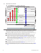
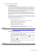
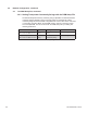
2.5 XP-DSM Start-up and Reboot Routine
The above diagram, read left to right, indicates the order of operations as the transponder comes
online. There are certain conditions that must exist for each step to occur, resulting in successful data
monitoring and management. The numbers below correspond to the numbered arrows above.
When the XP-DSM is installed and powered-up, it nds the DOCSIS frequency being used by the
Cable Modem Termination System (CMTS), and establishes communication.
The CMTS communicates with the DHCP server to get an IP address for the XP-DSM’s cable
modem. The DHCP server must be provisioned with the XP-DSM’s cable modem RF MAC
address for it to recognize the modem as a valid device (Section 3.1). This means the cable
modem’s RF MAC address must be assigned a specic DOCSIS Conguration File, stored in the
TFTP root directory of the TFTP server (Section 3.2).
Once the modem is given an IP address, it is synchronized with the network through the Time of
Day (TOD) Server.
As the modem comes online, the XP-DSM downloads the DOCSIS Conguration le from the
THCP Server, which sets modem options (see Section 3.2).
The XP-DSM transponder’s options are set according to the DSM Setup File (if used). In Dual IP
Mode, the XP-DSM transponder is given its own IP address as a CPE to the modem (see Section
2.2).
Time
Cable Modem
DSM Transponder
DHCP Server Web Browser
MIB Browser
Network Management System
CMTS
Network Devices
TOD Server
TFTP Server
Local Laptop
1 2 3
4
5
6
6c
6b
6a
7
TCP/IP NetworkHFC Network
1
2
3
4
5