
Quick Start Guide Manual

3746-257-B0-001 Rev. A (2/2014)
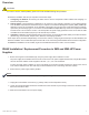
Overview
IDH4 Series installation and setup is comprised of three basic steps:
1. Conguring the Network: Provisioning the DHCP Server with the transponder’s MAC Address and assigning it a
DOCSIS Conguration File.
2. Setting Options: The IDH4 Series is designed for out-of-the-box, "plug and play" operation, but non-default settings
such as SNMP trap destination addresses may be required for the Network Management System (NMS). SNMP trap
addresses can be set automatically via the DOCSIS Conguration File per RFC 4639, while IDH4 Series proprietary
options may be set through type-11 TLV entries. The SCTE-HMS and Alpha MIBs may need to be compiled into a MIB
browser before it can be used to monitor or set transponder and power supply parameters. Refer to the IDH4 for XM2
and XM2-HP Technical Manual (Alpha p/n 746-257-B2-001) for details.
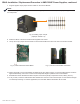
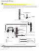
3. Installation: Installation of the IDH4 Series into the power supply, connecting the RF Cable, battery sense wire harnesses
(IDH4X only), Environmental, Tamper switch, Ethernet, and verifying operation.
These steps can be performed independently of one another. However, conguring the network prior to eld installation will
allow the installation to be veried while personnel are still on-site. Performing eld installation before network conguration
and before the installation can be veried, might result in additional eld service calls to correct mistakes.
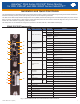
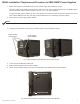
1. Before removing the Inverter Module (IM), verify the power supply device address is correct.
The power supply device address must not be set to zero and no two power supplies monitored by a single IDH4 Series
can have the same address. Power supplies must have 1, 2, 3, 4 or 5 as an address.
To verify the power supply’s address, go to the LCD display on the inverter module and enter the "Setup" menu. Scroll
to the "Device Address" menu item and verify the device address is set to something other than 0 (Zero).
2. Switch OFF the power supply’s battery breaker.
3. Unplug all Inverter Module connections (e.g. battery cable, remote temperature sensor).
4. Loosen the Inverter Module thumbscrews and slide the inverter module out just enough to disconnect the ribbon cable.
Disconnect the ribbon cable.
5. Slide the Inverter Module out of the power supply.
NOTE:
With the battery breaker in the OFF position, the power supply will not go into inverter mode.
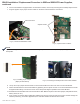
IDH4X Installation / Replacement Procedure in XM2 and XM2-HP Power
Supplies
CAUTION!
For units in service, backup battery power will not be available during this procedure.