
User Manual


10
745-838-B2-001 Rev. A
2.0 Installation
Before installing the XP-EDH-A2 into a power supply, review your system requirements and
determine the number of cable assemblies you need to monitor your HFC standby power supplies.
The procedure for installing the XP-EDH-A2 into any supported power supply involves general information,
(information that is common to all the power supplies), and information specifi c to an individual type of power
supply. These installation instructions are divided into two sections to refl ect this. It is recommended that you
read through the general instructions and then take note of any information specifi c to your power supply.
Also, installation of this product involves both fi eld installation and the confi guration of the system, including
network security, SNMP set-up, and other system provisioning. While those two procedures are handled
independently, they are presented together in the section specifi c to your power supply.
2.1 General Installation Information for Supported Power Supplies
NOTE:
There are a few basic steps to follow to install the XP-EDH-A2 into supported power supply
sites. The steps are either fi eld steps or system confi guration steps, and can be performed
independently.
Field installation steps are:
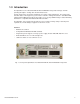
Transponder Placement1.
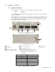
Disconnecting the DC power2.
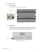
Confi guring the Interface Card3.
Wiring the battery harness4.
Connecting the power supply interface and measurement cables5.
Confi rming the RF drop6.
System confi guration steps are:
Provisioning Network Connectivity7.
Confi guring the MIBS8.
Setting the DOCSIS confi guration fi le options9.
Completing and Testing the installation:
Verifying the operation10.
Detailed information on each of these steps follows.
Note the following:
The types and quantities of each power supply type•
Number of individual batteries per site (if you plan to increase the number of batteries in the •
future, consider ordering additional battery harnesses)
Length of required battery harness (The standard 4 ft length battery harness is used in the typical •
power supply cabinet where one to three battery strings are mounted in the trays underneath the
power supply shelf. If necessary, a 20 ft battery harness is available)
The required type of interface cards (RPM, USM, USM2.5, etc.)•
Utility power available at the site, 110V or 220V.•