
User Manual

18
745-838-B2-001 Rev. A
3.0 Installation Instructions for Specifi c Power Supplies, continued
3.1 Alpha XM2 Series, continued
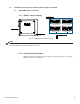
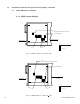
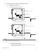
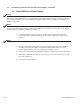
3.1.5 Connecting the XP-EDH-A2 to an XM2 Series Power Supply
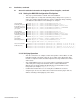
Below is a cable installation guide diagram with interface, four batteries and power to
an Alpha XM2 power supply with DC powering.
Fig. 3-6, XM2 Series Installation with Four Batteries
UNLATCH RIBBON CABLE RETAINER
BEFORE FULLY REMOVING MODULE.
OUTPUT 1
OUTPUT 2
N + 1
SSR
OUTPUT
N
L
LRI
WHT
RED
BLACK
BATTERY
BLK
INPUT
BREAKER
BATTERY
X M
S E R I E S
transformer
m o d u l e
module
inverter
ALARM
OUTPUT
ESC
M
TEMP
PROBE
RED
BLACKBLACK
RED
TEST
13 PIN CONN
S
S
C
O
Y
TMPR
Power Supply
PWR
Power
110V AC Line Input
POWER SUPPLY CABLE
14 PIN
RF CABLE IN
SYSTEM
US
DS
Battery
18 PIN
16 PIN
BATTERY CABLE
PLACE
TEMP PROBE
BETWEEN
BATTERIES
B
L
ACK
BATTERY 1
BATT
TEMP
PROBE
-V
BATTERY 2
+
1
2
V
BLACK
+
2
4
V
+V
BATTERY 3
+
3
6
V
BATTERY 4
RED
RE
D
BATTERY STRING 1
( OPTIONAL )
ONLINE
DOCSIS Transponder
AlphaNet
R
0A C4 36
N + 1
Power Supply Interface Cable
USM2 power
supplies only
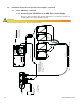
CAUTION!
Improper wiring may damage the unit and void the warranty.
Installation Note:
The + battery terminals
face the front of the
enclosure
Important!
Plug in the 13 pin connector
toward the bottom of the
header so two pins remain
open at the top of the header
for the Tamper Switch cable.