
User Manual

21745-838-B2-001 Rev. A
3.2.1 XM Series Jumper Settings
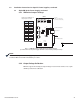
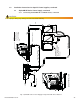
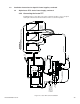
Fig. 3-7, XM/XP Power Supply Universal Status Monitor
(as viewed from rear of power supply with main control module partially removed)
Jumper Position
P1 2-3
P2 open
P3 open
P4 closed
P5 closed
P6 closed
P7 5V
P8 1-2
P9 1-2
P13 1-2
P14 1-2
SW4 0
SW1
DC
1
2
3
Remove the USM and set
the jumpers as follow:
Set to 0
(SWs 1,2,3 may not be
present on some boards)
Potentiometer Adjuster
RJ Connector
Power Supply Interface
SW2 SW3 SW4
R8
12
12
12
1
1
1
P1
P2
P3
P4
P5
P6
P7
5V
24V 15V
P8
P9
P13
P14
AC
CUR
AC Volts
1
2
3
1
2
3
1
2
3
USM
3
PIN 1
Legend:
Pins jumpered
3.0 Installation Instructions for Specifi c Power Supplies, continued
3.2 Alpha XM Series Power Supply, continued
NOTE:
The switch settings in this section apply only to the EDH-A2 and differ from the EDH-A. Refer to the EDH-A
Installation Manual for EDH-A installation procedures.
3.2.2 Output Voltage Calibration
EDH-A2 supports AC Scaling for Output Voltage measurements and does not require
USM2.5 potentiometer calibration.