
User Manual

22
745-838-B2-001 Rev. A
3.0 Installation Instructions for Specifi c Power Supplies, continued
3.2 Alpha XM Series Power Supply, continued
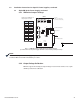
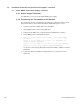
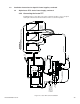
3.2.3 Connecting the XP-EDH-A2 to an XM Series Power Supply
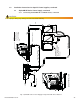
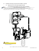
Follow the diagram below to make all connections between the transponder and the
power supply site. The diagram is the cable installation guide drawing with interface,
three batteries, and power to an Alpha XM power supply.
RED
B
L
A
C
K
POWER SUPPLY
INTERFACE
P
o
w
e
r Sup
p
ly
P
W
R
Pow
e
r
110V AC Line Input
POWER
SUPPL
Y
CABLE
1
4
PIN
R
F CABLE I
N
SYSTEM
US
DS
Ba
tt
ery
18
P
I
N
16 PIN
C
BL-PS-BAT-04-0
0
4
(
4
FT LO
N
G)
BATT
E
RY
C
A
BL
E
PLACE
TEMP P
RO
B
E
BETWEEN
B
A
TT
ERIES
B
L
A
C
K
BATTERY
1
B
AT
T
TE
MP
PROB
E
-V
BA
TTER
Y
2
+12V
B
LA
C
K
+24V
B
A
TTER
Y
3
+
V
RED
+3
6V
BATTER
Y
S
T
R
I
NG
1
F
u
s
e
WAR
N
I
N
G
:
3
I
ND
I
C
A
TOR
L
AM
P
R
E
M
OT
E
ST
AT
US
R
E
L
A
Y
ST
AND
B
Y
1
2
O
UTP
UT
4
6
5
A
C
BLACK
R
E
D
BATTE
R
Y
C
O
N
N
E
C
T
OR
+
C
I
R
C
UIT
B
R
E
A
K
E
R
-
BATTE
R
Y
OF
F
Al
p
ha
S
E
R
I
E
S
Tec
hn
ol
i
gi
e
s
X M
B
LA
C
K
RED
WIRE
YELLOW
1
8
PIN
Bat
tery
Bl
ack
wire
Red/Green
wire
View
Side
Cut
Here
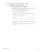
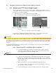
CUT AND REMOVE A
PIECE OF
RED/GREEN WIRE IF PRESENT
FOR XM SERIES ONLY
!
CUT THE WIRE
I
N UPPER LEFT POSITION
A
S SHOWN. ANY WIRE
COLOR.
DO
CSIS Transponder
A
lphaNet
0A C4 3
6
ON
L
I
NE
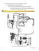
Fig. 3-8, XM Series Installation with Three Batteries
CAUTION!
Improper wiring may damage the unit and void the warranty.
Installation Note:
The + battery terminals
face the front of the
enclosure
Important!
Plug in the 13 pin connector
so the black wire is in pin one
(the top pin) and two open
pins are left at the bottom for
tamper switch connection.