
User Manual

25745-838-B2-001 Rev. A
3.0 Installation Instructions for Specifi c Power Supplies, continued
3.3 Alpha AM/AP Series Power Supply, continued
3.3.1 Connecting the XP-EDH-A2 to a AM/AP Series, continued
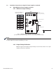
POWER SUPPLY INTERFACE
Power Supply
PWR
Power
110V AC Line Input
POWER SUPPLY CABLE
14 PIN
RF CABLE IN
SYSTEM
ONLINE
US
DS
16 PIN
CBL-PS-INTRFC-01-001
Battery
CBL-PS-BAT-04-004
18 PIN
BLACK
LARGER PARTIAL VIEW
DOCSIS Transponder
AlphaNet
R
0A C4 36
BLACK
RED
+
-
4
3
2
8
7
6
10
COM
+
NO
BLACK
NC
RED
BLACK
AM/AP
S
E
R
I
E
S
PIN 1
BLACK WIRE
+12
V
BATTERY STRING 1
+
2
4
V
BATT
TEMP
PROBE
PLACE
TEMP PROBE
BETWEEN
BATTERIES
BATTERY 3
RED
+V
BLACK
RED
T
e
c
hn
o
lig
ie
s
A
l
p
h
a
RED
-
BATT
1
OUTPUT
LAMP
9
5
BATTERY CABLE
POWER SUPPLY INTERFACE
CBL-PS-INTRFC-01-002
A
l
p
h
a
S
E
R
I E
S
T
e
c
h
n
o
lig
i
e
s
A
M/
AP
TO
BATTERIES
BLACK
RED
1
2
3
4
5
6
7
8
9
10
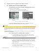
WARNING:
NO
COM
NC
LAMP
OUTPUT
BATT
+
-
RED
BLACK
BATTERY 1
BLACK
BATTERY 2
+36
V
B
L
ACK
-
V
RED
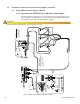
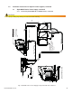
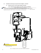
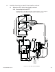
Fig. 3-9, AM/AP Series Power Supply, Transponder with Three Batteries
CAUTION!
Improper wiring may damage the unit and void the warranty.
Installation Note:
The + battery terminals
face the front of the
enclosure
Important!
Plug in the 13 pin connector
to the right as shown so the
two open pins for the tamper
switch connector are to the
left. If present, cut the Violet
wire.