
User Manual

28
745-838-B2-001 Rev. A
3.0 Installation Instructions for Specifi c Power Supplies, continued
3.4 Alpha/Lectro ZTT+ Series Power Supply, continued
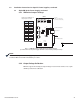
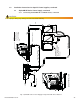
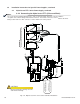
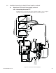
3.4.2 Connecting the Alpha/Lectro ZTT+ (Silver and Black)
US
T
AM
P
E
R
CBL-PS-INTFC-02-003
G
RO
U
ND
PWR
INTERFACE CABLE
POWER SUPPLY
RF CABLE IN
SYSTEM
18 PIN
Power SupplyPower
DS
Battery
GROUND
TAMPER
ONLINE
AC
FAULT / STANDBY
V A
NORMAL
ALERT
60/90 VAC
ON
DC
OFF
BATTERY
_
+
MULTIPLE POWER INPUTS
TURN OFF BOTH SWITCHES
TO FULLY REMOVE POWER
CABLE
AC OUT
ZTT / Plus
36 VDC
TO
LOAD
+
S
LVR
+
BLK
Z
TT
WITH TRANSFORMER
9VAC
120VAC
TO
POWER OUTPUT CABLE
BLACK
RED
+V
+24V
+
1
2
V
+3
6V
-
V
BATT
TEMP
PROBE
PLACE
TEMP PROBE
BETWEEN
BATTERIES
BLACK
RED
BATTERY CABLE
BATTERY 1 BATTERY 2 BATTERY 3
R
E
D
B
L
ACK
DOCSIS Transponder
AlphaNet
R
0A C4 36
BLACK RING DIN , ZTT+
MOVE THE SWITCH ON CABLE ASSY
TO THE " +BLK " POSITION
SILVER RING DIN , ZTT+
MOVE THE SWITCH ON CABLE ASSY
TO THE " +SLVR " POSITION
Fig. 3-11, Alpha/Lectro ZTT+ Series Silver and Black Installation
NOTE:
The Lectro ZTT+ installation diagram is the same for both the black and silver connector with the
exception of the switch setting on the interface harness. For a black connector, set the switch to the ZTT+
black position and for a silver connector, set the switch to the silver position.
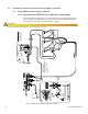
CAUTION!
Improper wiring may damage the unit
and void the warranty.
Installation Note:
The + battery terminals face the front of the enclosure