
Instruction Manual

Doc. #: 0260011-J0 Rev B
14
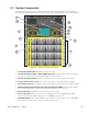
10. Rectifier Modules (optional): Up to one rectifier per
shelf. The rectifiers are used as the charging component
of a 3i+1R shelf system.
11. Fus e for the graphic display for the CXCU, and V+/ V- to
the controller
12. Fuse for customer use 2A load, pins #5 and #6 on 8-pin
terminal strip—see section 2.3.1 on page 15.
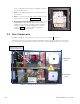
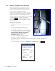
13. Surge Suppression Modules (behind removable
panel) built into the power distribution panel to protect
equipment from damage caused by surges and high
transient voltages. The surge suppression modules,
shown in Figure 2, short to ground any unwanted
voltages above a safe threshold.
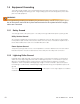
Figure 2 — Surge Suppression Modules
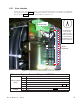
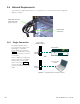
2.3 Rear Components
AC and DC wiring are accessed from the rear of the unit. See Chapter 5 for details.
A 3i+1R shelf system (one rectifier and three AIM1500 modules) has AC rectifier fuses that protect
the system from a wiring fault. Remove the back cover of the AC Wiring panel to access the fuses.
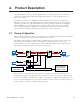
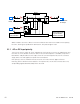
Figure 3 — AMPS24 HP rear view (with protective covers removed)
Remove grey cover to
change rectier fuses
AC distribution
panel
DC distribution
panel