
Instruction Manual

15
Doc. #: 0260011-J0 Rev B
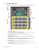
2.3.1 User Interface
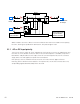
On the side of the unit are two connectors. The eight-pin terminal strip is an interface to the AMPS24
with the pinouts listed in Table A. The 40-pin connector is an interface to the CXCR controller with the
pinouts listed in Table B. Some pins are available for customer use.
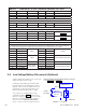
Table A — Eight-pin Terminal Strip from AMPS 24
Factory installed
wiring
1 TVSS2 alarm
2 Input circuit breaker (CB6) alarm
3 Maintenance bypass switch alarm
4 Output circuit breaker (CB5) alarm
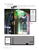
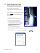
7 Fused DC-: 3A, CXCU LCD, V- to controller (fuse location shown in Figure 1)
8 DC+: CXCU LCD, V+ to controller
Customer
5 Fused DC-: up to 2A load, (fuse location shown in Figure 1)
6 DC+
40 pin
connector
8-pin
terminal strip
40
22
2
20
10
8
1
39
21
19
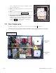
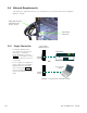
Figure 4 — Eight-pin terminal strip and 40-pin connector pin locations
To install wires
in the 40-pin
connector, use
needle-nose pliers
to remove the ter-
minal blocks in the
40-pin connector.