
Instruction Manual

Doc. #: 0260011-J0 Rev B
16
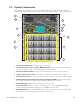
Table B — Pinouts for 40 Pin Connector Interface to CXCR
1 DIN1 2 DIN2 Output circuit breaker CB5
3 D_COM Fused DC- 4 DIN3 MBS
5 DIN4 6 DIN5 Input circuit breaker CB6
7 D_COM Fused DC- 8 DIN6 TVSS
Not Used
9 N/A 10 N/A
11 N/A 12 N/A
Analog Inputs
13 V1+ 14 T1+
Battery temperature probe
(Figure 6)
15 V1- 16 T1-
17 I1+ 18 T2+
Battery temperature probe
(Figure 6)
19 I1- 20 T2-
Relay Contacts (rated at 60VDC or 42V AC, 0.5A)
From the factory, the Cordex controller is congured with the relay assignments shown below. The relays can
be unassigned from their factory conguration and remapped. For example Relay 2, K2, can be unassigned
from LVD #2 then remapped as an alarm relay. Refer to the Cordex controller manual for details.
21 K1_NO
LVD #1
22 K2_NO
LVD #223 K1_NC 24 K2_NC
25 K1_COM 26 K2_COM
27 K3_NO
LVD #3
28 K4_NO
Power System Minor alarm29 K3_NC 30 K4_NC
31 K3_COM 32 K4_COM
33 Not installed 34 Not installed
35 K5_NO
Power System
Major alarm
36 K6_NO
AC Mains High/Low alarm37 K5_NC 38 K6_NC
39 K5_COM 40 K6_COM
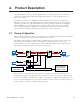
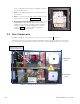
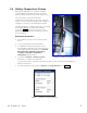
2.4 Low Voltage Battery Disconnect (Optional)
A built-in AMPS24 shutdown cuts off the load
during a lengthy power outage.
Installing an LVD (Alpha part number 020-
615-20), between the AMPS24 HP and the
batteries, disconnects the AMPS24 HP from
the batteries to prevent further drain of the
batteries during a lengthy power outage.
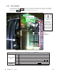
The controller is configured with a relay
assigned to LVD #1. Figure 5 shows how to
wire the normally closed contacts of the LVD
#1 relay to activate the LVD. The activation
value is set in the Controls >LVD C ontrol
menu—see the controller software manual.
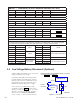
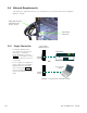
AMPS24 HP
LVD
LVD#1
K1 Relay
Pin 25
Pin 23
Pin 21
Batteries
-48V@Pin 3
Figure 5 — LVD wiring
Pinouts available at the AMPS24 40 pin connector
– see Figure 4 and (Table B.