
Instruction Manual


Doc. #: 0260011-J0 Rev B
50
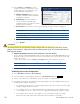
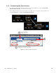
23. Select Inverters -> Set Output to set the
number of inverters in each phase of your
system. Match the AC input phase to the
corresponding AC output phase.
a. Number of Modules: Enter the total
number of inverter modules that will be
installed for that phase.
b. Redu ndancy: Enter the number of
inverter modules that will provide
redundant power for that phase (used to
provide system warnings).
c. Pha se Shift: Enter the phase shift for each output group in your system configuration
1 2 3
Single phase ° 0 N/A N/A
Split phase (120/240 V) ° 0 180 N/A
2-pole (120/208) ° 0 120 N/A
3-phase (120/208 V) ° 0 120 240
d. Nominal Outp ut Voltage: Enter 120 for all phases.
e. Press Submit.
CAUTION!
The value entered in the Nominal Output Voltage eld can change the actual AC output
voltage of the inverters. Setting this value to anything other than 120 V will render the UL/
CSA approval invalid.
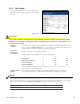
24. D O NOT PROCEED if there are alarms (Inverters > View Live Status) .
Alarm code (41) PHASE NOT READY and/or (175) AC OUT NOT SYNCHRONIZED indicate that
the phase rotation of the AC Input is not correct. (The inverters will not start until the phase and
rotation are correct.)
To remove the alarm, return to Inverters -> S et Output and correct the phases as shown:
1 2 3
2-pole (120/208 V) ° 0 240 N/A
3-phase (120/208 V) ° 0 240 120
25. If the alarms do not clear, go back to step 20 and repeat all steps.
Validating the inverter configuration
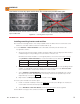
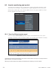
26. Select Main Menu > Inverters > Group Mapping.
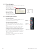
27. Turn the inverters on by clicking the power icon Turn All Modules On (see Figure 31).
28. Switch on the Inverter AC output breaker on the front panel of the AMPS24 HP.
29. Check the actual Inverter AC Output by measuring voltages on the AC Output terminal block in
the AMPS24 HP wiring compartment:
a. The voltage from Neutral to L1 / L2 / L3 is approximately 124 V. At no load, the inverter output
voltage is slightly higher than nominal.
b. The voltage from L1 to L2 is approximately 240 V for a split phase system, 208 V for 2-pole,
or the voltage from L1 to L2, L2 to L3, L3 to L1 is approximately 208 V for a 3 phase system.
c. The voltage from AC Input L1 to AC Output L1 is less than 30 V. Similarly, the voltage
between L2 input and output and L3 input and output should be less than 30 V.
Figure 32 — Set Output (Split Phase System)