
Instruction Manual


57
Doc. #: 0260011-J0 Rev B
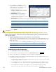
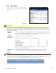
6.2.1 Set Output
Number of
modules:
The value is the number to be acquired by the CXCU. An invalid setting will result in an
alarm condition: Inverter Comms Lost; i.e., the number of modules must agree with the
actual number of inverters mapped to that particular group.
Amount of
Redundancy:
Number of inverters considered redundant
Phase shift:
Assign a phase shift (in degrees) to the AC output group
1 2 3
Single phase 0 N/A N/A
Split phase (120/240 V) 0 180 N/A
2-pole (120/208 V) 0 120 N/A
3-phase (120/208 V) 0 120 240
If the actual phase rotation of the AC Input is not 1 – 2 – 3 (i.e. it may be 1 – 3 – 2),
alarms will result. See NOTE below.
Nominal Output
Voltage
Sets the target output AC voltage and must be used with caution; the devices
connected to the inverters could sustain damage due to irregular AC voltage.
Verify that the Phase Shift is set correctly before
mapping inverters in the new groups and turning
them on.
Figure 38 — Set Output window
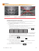
Alarm code (41) PHASE NOT READY and/or (175) AC OUT NOT SYNCHRONIZED indicate that the phase
rotation of the AC Input is not correct. (The inverters will not start until the phase and rotation are correct.)
To remove the alarm, return to Inverters -> S et Output and correct the phases as shown:
1 2 3
2-pole (120/208 V) ° 0 240 N/A
3-phase (120/208 V) ° 0 240 120
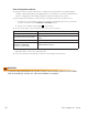
NOTE:
CAUTION!
The value entered in the Nominal Output Voltage eld can change the actual AC output
voltage of the inverters. Setting this value to anything other than 120 V will render the UL/
CSA approval invalid.