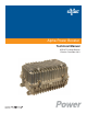
Alpha Power Booster Technical Manual APB HFC Voltage Booster Effective: December 2011
Power Alpha Technologies ®
Alpha Power Booster APB HFC Voltage Booster 016-559-B0-001, Rev. A Effective Date: December, 2011 Copyright © 2011 Alpha Technologies, Inc. member of The GroupTM NOTE: Photographs contained in this manual are for illustrative purposes only. These photographs may not match your installation. NOTE: Operator is cautioned to review the drawings and illustrations contained in this manual before proceeding.
Contents Safety Notes .......................................................................................................................... 6 Safety Precautions ................................................................................................................ 6 1.0 2.0 System Overview ........................................................................................................ 7 1.1 Introduction ................................................................................
Figures Fig. 1-1, APB Voltage Booster .................................................................................... 7 Fig. 1-2, APB Internal Components ............................................................................ 8 Fig. 2-1, Label with Factory Config Field ...................................................................11 Fig. 2-2, Configuration Connect .................................................................................11 Fig. 2-3, Coaxial Cable Connector.............
Safety Notes Review the drawings and illustrations contained in this manual before proceeding. If there are any questions regarding the safe installation or operation of this product, contact Alpha Technologies or the nearest Alpha representative. Save this document for future reference. To reduce the risk of injury or death, and to ensure the continued safe operation of this product, the following symbols have been placed throughout this manual. Where these symbols appear, use extra care and attention.
1.0 System Overview 1.1 Introduction The Alpha Power Booster (APB) was created to improve network efficiency and reduce life cycle cost by eliminating lightly loaded power supplies at the end of long amplifier cascades. The voltage booster accomplishes this by boosting end-of-line voltages. The voltage boost allows deeper penetration of the HFC network and eliminates the need for power supplies and batteries near the end of the HFC network. Fig. 1-1, APB Voltage Booster 016-559-B0-001 Rev.
1.0 System Overview, continued 1.2 Internal Components Output Input Step-up Autotransformer Tap-switch PCBA RF Module with Input and Output Connectors Fig. 1-2, APB Internal Components 8 016-559-B0-001 Rev.
2.0 Installation 2.1 Enclosure Installation 2.1.1 Strand Mounting Tools Required: • 1/2” Socket • 0-100 in-lb torque wrench Procedure: 1. Loosen the two strand clamps on the enclosure. Ensure that the side labeled "INPUT" is facing the correct direction. 2. Place the strand wire under the clamp plates and torque the bolts to 75 in-lbs. 3. Ensure that the output voltage is configured properly. Refer to section 2.2 if the output voltage requires changing. 4.
2.0 Installation, continued 2.1 Enclosure Installation, continued 2.1.2 Surface Mounting Tools Required: • 1/2” Socket • 0-100 in-lb torque wrench • Drill • 3/8” drill bit Procedure: 1. Loosen the two strand clamps on the enclosure. Ensure that the side labeled "INPUT" is facing the correct direction. 2. Verify that the mounting surface is flat between the mounting locations prior to drilling. 3. Drill two 3/8” holes that are 10” apart. 4. The threaded holes in the enclosure are 1/2” deep.
2.0 Installation, continued 2.2 Output Voltage Configuration Tools Required: • True RMS Volt Meter • Clamp-On Amp Meter 1. Note the factory configured output voltage by reading the label on the side of the housing. The label has a field named FACTORY CONFIG that will be filled with either 63Vac or 87Vac. Fig. 2-1, Label with Factory Config Field 2.
2.0 Installation, continued 2.3 Cable Preparation Tools Required: • Wire Cutters • Open-End wrenches (refer to manufacturer’s assembly instructions) WARNING! Coaxial cables may carry AC power. To avoid possible shock or damage to the equipment, always handle coaxial cables with extreme caution. Always install coaxial connectors with the RF module removed from the enclosure. NOTE: This section is for reference only; follow instructions provided by the connector’s manufacturer. Procedure: 1.
2.0 Installation, continued 2.3 Cable Preparation, continued Installation is complete. Go to Power Up and Test (Section 2.7, Power Up and Test). 3. Locate the measuring gauge near port number 1 or 2. 4. Place the connector’s collar against the edge of the measuring gauge molded into the enclosure. 5. Using heavy duty wire cutters, clip the pin as close to the line as possible. 016-559-B0-001 Rev.
2.0 Installation, continued 2.4 RF Module Removal Tools Required: • No. 2 Flat head screwdriver Procedure: 1. Disconnect the two Molex connectors (Output, J4, Input, J5). 2. Loosen the two captive screws near the center of the module. 3. Grasp the pull rings with your index fingers and pull firmly away from the enclosure. Disconnect per step 1 Pull Ring Captive Screws Pull Ring Disconnect per step 1 Fig. 2-4, RF Module Removal Fig. 2-5, RF Module Removed 14 016-559-B0-001 Rev.
2.0 Installation, continued 2.5 Coaxial Cable Attachment Tools Required: • 5/8” socket wrench with 6” extension • 20-200 in-lb torque wrench Procedure: 1. Remove the two seizure connectors from the enclosure. Fig. 2-6, Seizure Connector NOTE: Verify center conductor is centered in the groove in the plastic base. 2. Insert the prepared coaxial connector into the desired port (1-input; 2-output) and torque to 180 in-lbs. 3. Replace the seizure connectors and torque to 90 in-lbs. Fig.
2.0 Installation, continued 2.6 RF Module Reinstallation Tools Required: • No. 2. Flat head screwdriver • Torque screwdriver Procedure: 1. Firmly seat the module over the seizure connectors, with the open side facing AWAY from the circuit board. 2. Tighten the captive screws to 18 in-lbs. WARNING! The enclosure may become electrified if mis-wired or in the event of an internal short. Measure the voltage between the enclosure and earth ground before touching with bare hands. 3.
2.0 Installation, continued 2.7 Power Up and Test 2.7.1 Initial Power Up Tools Required: • True RMS Volt Meter • Clamp-On Amp Meter WARNING! There will be up to 90Vac present on the PCB when a live connector is plugged into the input or output connectors. 2 Procedure: 1 1. Plug the Output Connector from the RF Module into the J4 Output Connector (item 1) of the PCB. 2. Plug the Input Connector from the RF Module into the J5 Input Connector (item 2) of the PCB.
2.0 Installation, continued 2.8 Final Assembly Tools Required: • 1/2” Socket • 0-100 in-lb torque wrench Procedure: 1. Close the cover of the enclosure, making sure no wires are being pinched. Tighten all bolts finger tight. 2. Tighten the enclosure cover bolts to 30 in-lbs, in the sequence shown. Repeat the procedure, tightening the bolts to 70 in-lbs. 6 4 1 2 3 5 Fig. 2-9, Cover Bolts 18 016-559-B0-001 Rev.
2.0 Installation, continued 2.9 Specifications Specifications Electrical Input Voltage 45-65Vac 60Hz / 65-90Vac 60 Hz Input Current 10 Amps RMS (max) Output Voltage 63Vac 60Hz / 87Vac 60Hz Output Current <8 Amps RMS (max) Output Rating 650 VA (max) Overload Protections 115% for 27 minutes Short Circuit Bypass mode, automatic recovery Overload Recovery Automatic Surge Resistance 6kV/3000A (IEEE C61.
2.0 Installation, continued 2.10 Troubleshooting Troubleshooting Guide Symptom Probable Cause and Solution No Output No Input Voltage 63Vac Config: Verify that no less than 45Vac is present on the input connector. 87Vac Config: Verify that no less than 65Vac is present on the input connector. RF Module Not Fully Seated Ensure the RF Module is fully seated and the captive screws are tight. Module should be flush with the rim of the lower half of the enclosure.
2.0 Installation, continued 2.11 Voltage Booster Service Tools Required: • No. 2 Phillips head screwdriver WARNING! There will be up to 90Vac present on the PCB when a live connector is plugged into the input or output connectors. 2.11.1 PCB Replacement Procedure 1. Unplug Input Connector from J5 of the PCB. 2. Unplug Output Connector from J4 of the PCB. 3. Unplug XFMR Connector from J1 of the PCB. 4. Loosen captive bracket screws at "4" (2 places). 5. Remove assembly. 6.
2.0 Installation, continued 2.11 Voltage Booster Service, continued Tools Required: • 11/32 Nutdriver WARNING! There will be up to 90Vac present on the PCB when a live connector is plugged into the input or output connectors. 2.11.2 Transformer Replacement Procedure 1. Unplug transformer connector from J1 of the PCB. 2. Unplug transformer quick connects from Configuration (P1) and P4 of the PCB. Note which connector is attached to the Configuration male connector (LOG63 or LOG87). 3.
this page intentionally blank
Alpha Technologies Inc. 3767 Alpha Way Bellingham, WA 98226 United States Tel: +1 360 647 2360 Fax: +1 360 671 4936 Alpha Technologies Ltd. 7700 Riverfront Gate Burnaby, BC V5J 5M4 Canada Tel: +1 604 436 5900 Fax: +1 604 436 1233 Toll Free: +1 800 667 8743 Alpha Industrial Power Inc.